Строительные материалыGEOSEC®#GEOSEC®#Renewal and restoration#Ground and foundation consolidation#Ground consolidation#Construction
GROUNDFIX® - Система мини-инвазивного бурения
GROUNDFIX® is an active, mini-invasive piling technology that uses special modular steel elements assembled and press-fitted into the ground by means of hydraulic jacks prefixed to the original foundation structure with high-strength anchor plates and mortars. GROUNDFIX® represents the structural solution for deeper Foundation consolidation with the aim of transferring loads to more load-bearing soils.
Installation of Micropiles.
For the installation of the GROUNDFIX® micropile, the anchoring and subsequent reinforcement of the built-up structure is required. In fact, the pile is slowly introduced into the ground at constant pressure, by means of a battery of elements, until the design solid horizon is reached.
At the end of the infixing process, before the pile is attached to the original foundation, it will still be possible to apply loads in excess of the operating loads, thus inhibiting the primary post-tensioning subsidence; in addition, it will be possible to carry out a load test for the final inspection of the Foundation consolidation work on each individual micropile. If necessary, surface expanding resin injections can be combined to restore contact between the original foundation and its laying surface, or to improve the thickening of the soil in the layer crossed by the pile. GEOSEC® ensures the constant presence on site of its own qualified technician, always in close collaboration with the central technical office of the headquarters and with the Works Management.
Technical Advantages.
The intervention has numerous advantages over traditional piling techniques, namely:
Possibility of testing the bearing capacity of each individual micropile;
Possibility of active pre-loading;
Absence of spoil;
Speed of construction time;
Reduced site impact;
Absence of vibrations during pile driving;
When the structure allows it, subsidence recovery will be possible.
TheSteel Modules
The GROUNDFIX® press-fitted pile system is based on the use of special steel modular elements with a diameter of 60/76/114 mm. These elements are preliminarily processed by processing centres authorised by the Ministry of Public Works Central Technical Service and in accordance with the Technical Regulations for Construction D.M. 10/01/2008 as amended and supplemented for the part concerning the processing of steel for the cutting and threading of micropile tubes.
Anchor Plates
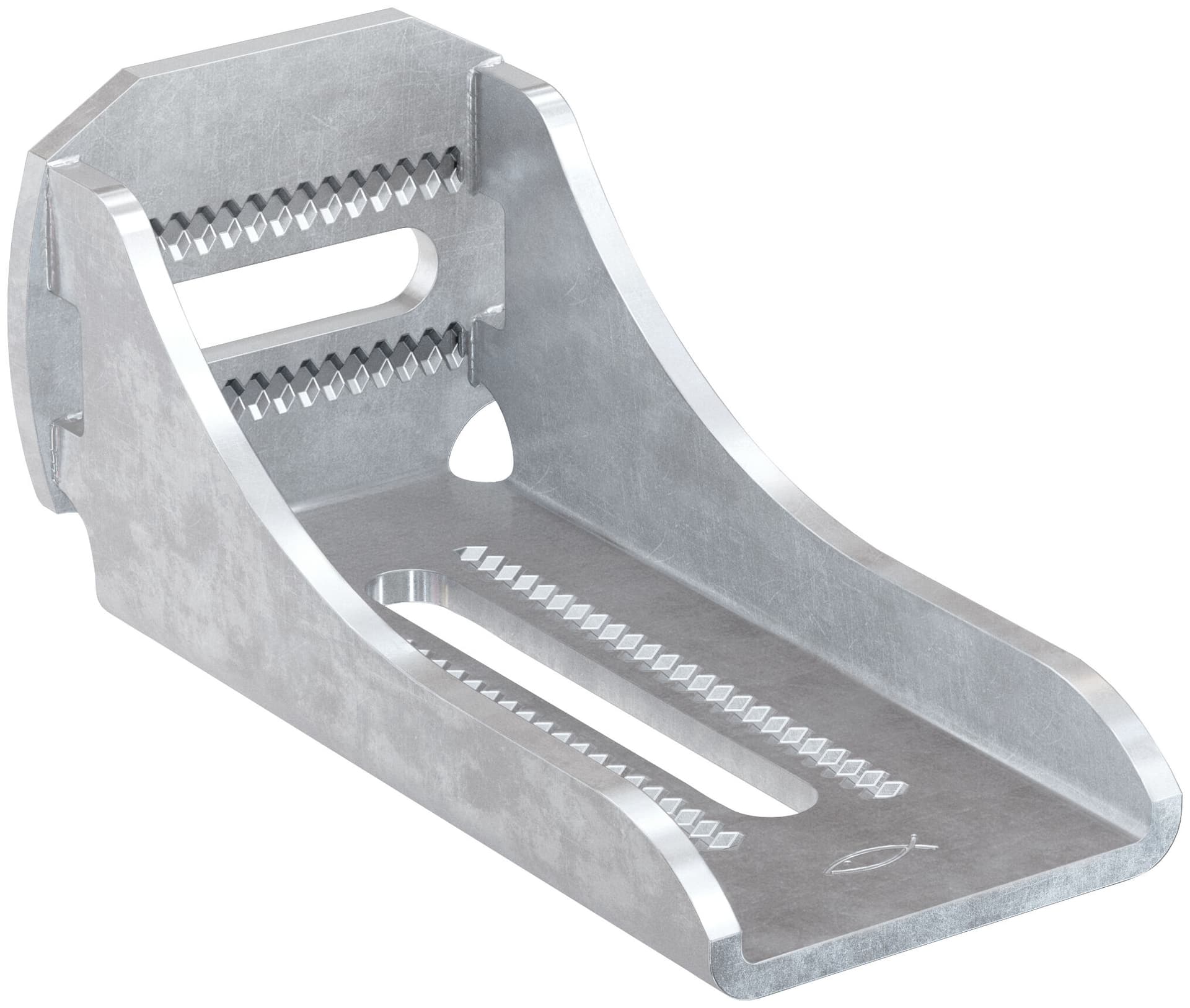
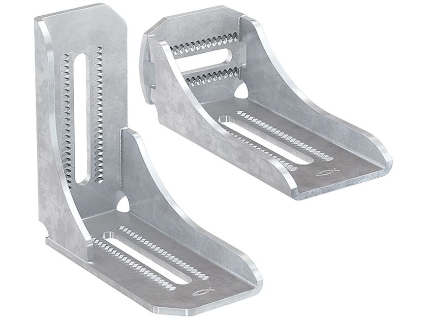
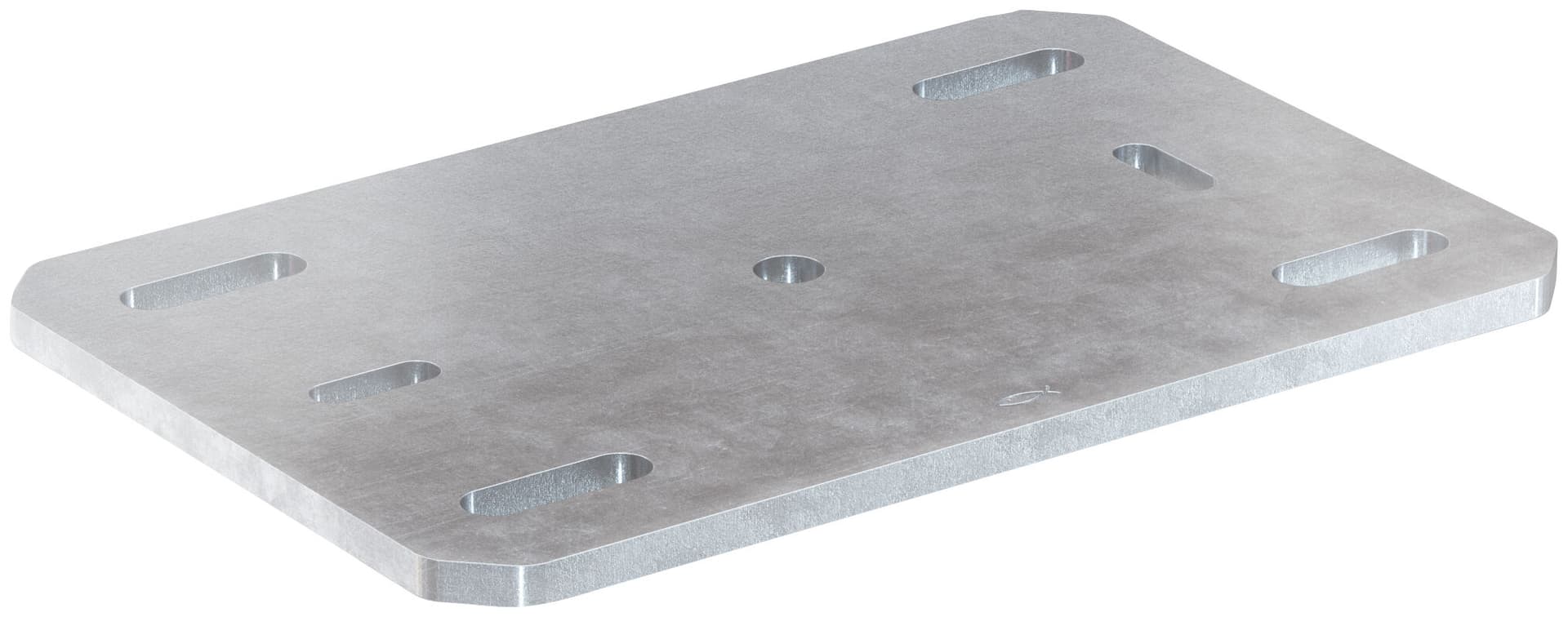
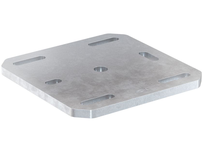
These elements are of fundamental importance for fixing the micropile thrust system until the end of driving. The plates can be of different sizes and geometry depending on the anchoring possibilities of the site and therefore the project. In the GROUNDFIX® line, plates are available for vertical lateral anchoring or to be embedded in reinforced rafts. Our carpentry is able to meet every design and operational need.
ThreadedPlate Fixing Bars
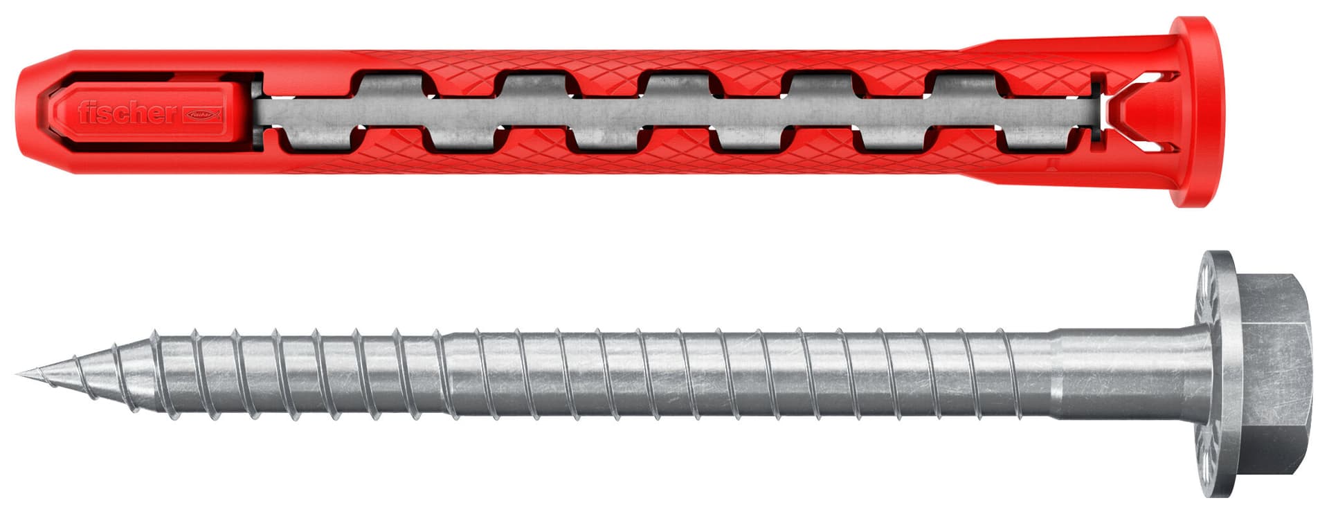
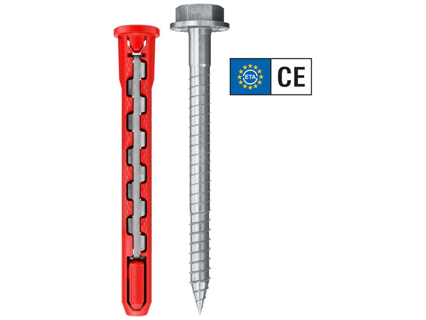
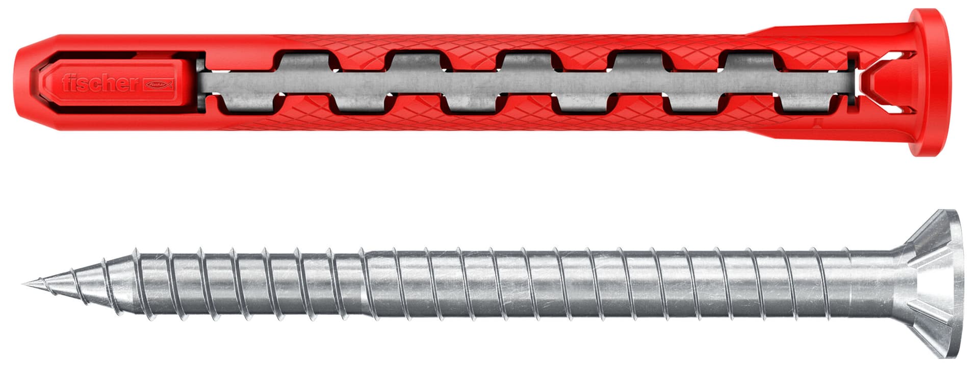
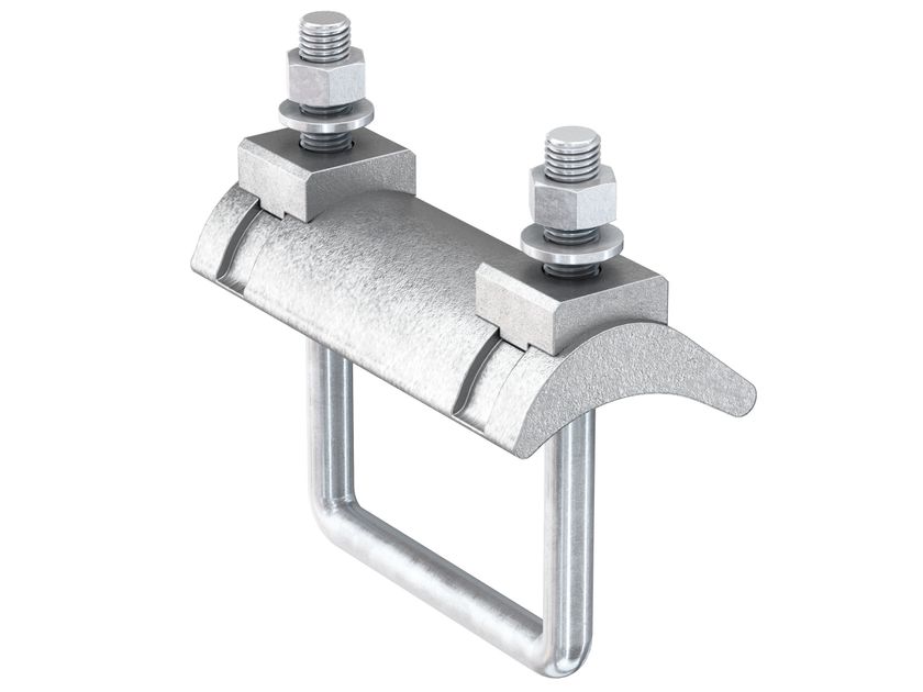
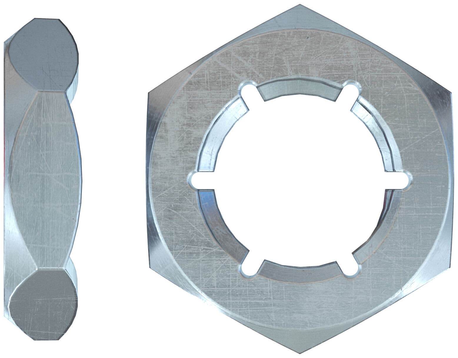
The threaded expansion anchor bars are made of galvanised steel with an oversized nut and washer for structural fixing of the plates to the existing foundation, and are CSTB certified by the French technical inspection body. Also ideal for seismic upgrades.
> Seismic qualification - Sizes M12 to M20 are approved for seismic performance in categories C1 and C2.
> Approved for design in fire exposure up to 120′.
> ETA Certificate Option 1 - can be used for tensioned (cracked concrete) or compressed (non-cracked) areas for safety-sensitive applications.
> quick insertion into hole with just a few hammer blows.
> fast tightening.
> full-length thread.
Thrust system
The installation of the post is carried out with the help of hydraulic jacks fixed to the foundation of the building by means of steel plates, which are firmly anchored to the foundation by means of special fastening elements consisting of 18 anchor rods. The cylinders with oil return for thrust and traction can guarantee a maximum operating pressure of up to 700 bar, with a stroke of 30-260 mm and a force of 5 - 25 t. The thrust energy is provided by a space-saving power station supplied by the GEOSEC® team, which in turn is powered by a generator set positioned on a workshop truck.
Fixing the Pile to the Pre-Existing Foundation
Once the pile has been driven in, the pile-foundation connection is made using the same steel plates used for driving in the pile, and the final plate-pile coupling is made using high-strength steel bolts, the final piece of tubular is cut to the height of the anchor plate. Below are the characteristics of the bolt:
TECHNICAL SPECIFICATIONS:
High-strength steel Class 10.9
Tensile strength at break: 1000 N/mm2
Limit of elasticity ≤ M20: 900 N/mm2
Metric thread ISO medium grade: 6g UNI 5541
REFERENCE STANDARDS:
Dimensional characteristics UNI EN ISO 5739
Mechanical characteristics UNI EN ISO 898
Inspection methods UNI EN ISO 3269
DESIGN AND VERIFICATION
GROUNDFIX®, Steel Micro-piles.
The Technical Solution.
The GROUNDFIX® press-fit pile system is based on the use of special modular steel elements with a diameter of 60/76/114 mm. The installation of the pile is carried out with the help of hydraulic jacks that are attached to the building foundation by means of special steel plates, which are firmly anchored to the foundation by means of special fastening elements consisting of 18 threaded anchor rods with a diameter of 18.4 mm. The foundation of the building and the overlying structure represent the contrasting set-up that allows the battery of elements to be easily driven in deep until the solid design horizon is reached. Once the pile driving is complete, the connection between the pile and the existing foundation is made using the same steel plates used for driving the pile, and the final plate-pile coupling is made using high-strength steel bolts.
Preliminary Activities and Design of the Intervention
LOAD TESTS ON PILE
Design tests on pilot piles N.T.C 2008 chap. 6.4.3.7.1 The most reliable method to determine the design resistance of the pile-soil system is to subject the pile to a load test. This consists of driving the pile to the design depth and applying a succession of loads (loading and unloading cycles) to the pile. Load tests are carried out on pilot piles and static load tests to verify the correct execution and behaviour under the design actions, as indicated by the N.T.C. 2008.
The design tests are pushed up to values of the axial load such as to bring the pile-soil complex to failure or in any case such as to allow significant diagrams of the failure of the pile head as a function of loads and times. The restraint system is sized to allow a test load value of not less than 2.5 times the design action used for SLE verifications. The strength of the pile-soil complex is assumed to be equal to the value of the applied load corresponding to a head failure equal to 10% of the diameter in the case of small and medium-diameter piles (d < 80 cm).
In the event that failure values are not reached during the test, it is possible to extrapolate the experimental curve provided that it shows a markedly non-linear behaviour of the pile-soil complex. The design tests for determining the strength of the individual pile are performed on specially constructed pilot piles identical in geometry and execution technology to those to be constructed and sufficiently close to them. In fact, for the robustness of the results deriving from the experiments and for them to be significant for the purposes of the project, it is essential that the pilot pile is:
> executed in the same manner as the piles of the piling;
> located within or in the immediate vicinity of the piling;
> located in the vicinity of boreholes and/or site tests, so that the results can be referred to a known geotechnical situation.
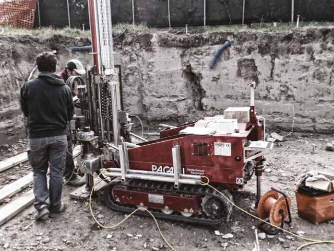
The behaviour of the piles can therefore also depend considerably on details of the construction procedure; for this reason GEOSEC® is also equipped to carry out the pilot pile in addition to the piles themselves in the project piling. Prior to the intervention and depending on the structural and environmental context, some preparatory work can be carried out, such as excavation work up to the foundation laying level, coring, smoothing, demolition, etc., necessary for the installation of the pile to the foundation. Everything is carried out with minimum inconvenience, as there is no need for heavy and cumbersome machinery that produces vibrations to the structures and requires more space.
Technical Validation of the Method
The technical standards for constructions as per D.M. 14.01.2008 (§ 6.4.3.7.2.) and C.M. no. 617 of 02.02.2009, prescribe that checks must be carried out on foundation micropiles during construction, checking their behaviour in relation to the expected and design values, in particular with regard to settlements. Static verification load tests must be carried out on the foundation piles, mainly to check their correct execution and behaviour under design actions. These tests must therefore be driven at an axial load of 1.5 times the design action used for SLE verifications. Operationally, for the application of the load, a hydraulic jack is used to force a specially prepared high-strength, high-stiffness contrast structure with a concentrated load in the centreline. The test is carried out following the instructions of C.N.R. 191/99.
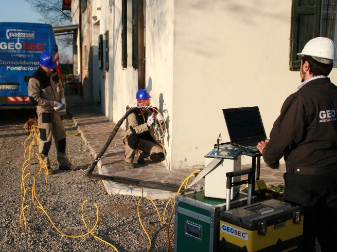
The test equipment consists of a hydraulic thrust system composed of a single-phase modular hydraulic power unit of 700 bar (7 kN/cm2), digital pressure gauge on the delivery of 1.000 bar, single 300 kN thrust hydraulic jack with a stroke of 50; the measuring system also acquires and records the applied force and displacements through readings at predefined intervals thanks to the 3 analogue centesimal comparators arranged at 120° on independent supports and the load cell placed between the piston and the pole. The equipment all has a calibration certificate from a qualified and authorised laboratory. The number and location of the verification tests shall be established according to the importance of the work and the degree of homogeneity of the foundation soil; in any case, the number of tests shall not be less than - 1 if the number of piles is less than or equal to 20,
> 2 if the number of piles is between 21 and 50,
> 3 if the number of piles is between 51 and 100,
> 4 if the number of piles is between 101 and 200,
> 5 if the number of piles is between 201 and 500,
> the nearest whole number to the value 5 + n/500, if the number n of piles is greater than 500.
> The number of verification load tests may be reduced if dynamic load tests are carried out, to be calibrated with the static design load tests, and non-destructive testing is carried out on at least 50% of the piles.
Normative References
For the execution of the tests and the processing of the data, reference has been made to the following standards:
> Technical Standards for Construction (NTC2008), D.M. 14/01/2008
> Circular of 2 February 2009 no. 617 - Instructions for the application of the "New Technical Standards for Construction" referred to in D.M. 14 January 2008.
> Standard CNR 191/99 ("Procedure for the execution and interpretation of axial compression load tests on foundation piles").
> Eurocode 7 - Geotechnical Design - Part 1: General Rules
0
0