

Управление строительствомGRAPHISOFT Italia#GRAPHISOFT Italia#Software#BIM, CAD and rendering#2D & 3D CAD technical design#CAD-integrated building services software
GRAPHISOFT Italia MEP Modeler
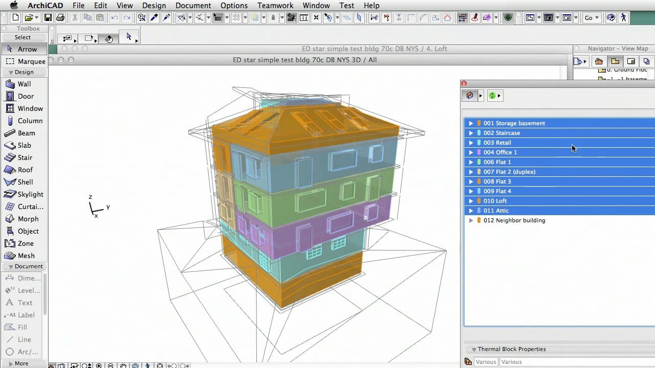
GRAPHISOFT MEP Modeler™ is an Add-On for ARCHICAD® that allows ARCHICAD users to create and modify 3D MEP plant networks (piping, piping and cabling) based on the model, i.e. perfectly coordinated with the Virtual Building developed with ARCHICAD. MEP Modeler uses a familiar interface and its tools are also integrated into the ARCHICAD environment.
MEP Modeler - Presentation
Among the main causes of budget overruns in the construction industry is poor coordination between the different actors involved. For both contractors and designers looking for a reduction in costs due to poor project coordination that is reflected on the construction site, MEP Modeler is an excellent solution.
MEP Modeler also increases ARCHICAD's possibilities in importing IFC models with MEP elements derived from other software, and collision detection can therefore also take place between elements of the MEP system and those of the architectural project.
BIM or 2D Workflow
Whatever the installer's method of producing a 3D project, ARCHICAD can import it using the IFC format, but in addition to a "generic" IFC import, the MEP Modeler package has more refined solutions towards MEP BIM applications (such as Revit MEP, AutoCAD MEP, DDS-CAD MEP, MagiCAD etc.).).
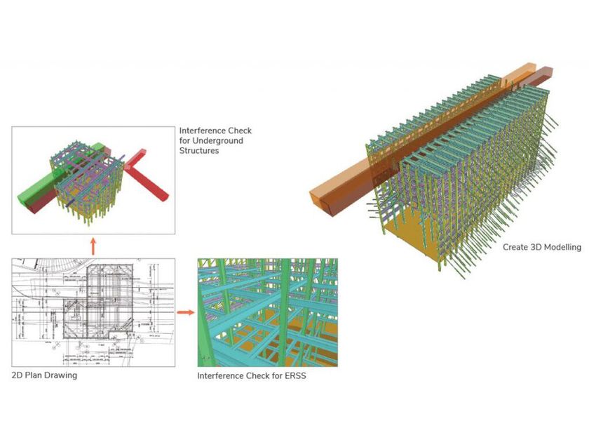
Although the plant design is delivered in 2D, with MEP Modeler it is very easy to return it and modify it in 3D to check for possible collisions.
MEP Modelling
MEP Tools
The MEP Modeler toolset allows you to create MEP components of various types:
- straight, curved and flexible HVAC ducts, pipes and routing for electrical wiring;
- transitions, splices, in-line elements to connect the different MEP components;
- connectors and terminals for automatic intake and output connection of MEP systems.
The MEP elements are all parametric, easy to dimension and configure.
MEP Object Library
GRAPHISOFT MEP Modeler comes with an extensive library of specific objects, with many MEP elements equipped with special intelligent anchor points for automatic joining when designing MEP systems. After the installation of MEP Modeler, some objects in the ARCHICAD library (e.g. for sanitary appliances, kitchen furniture, heating systems, etc.) will also see their potential extended thanks to intelligent anchor points and other parameters specific to MEP systems.
Personal MEP Elements
MEP objects can be created and saved simply by using the standard ARCHICAD tools such as Walls, Slabs, Shapes and Objects (GDL). New objects will automatically be added to the current MEP Library, so they can be used in the current project or reused in other projects. Personal MEP elements have the same intelligent behaviour as the standard MEP objects contained in the MEP Modeler package.
MEP Systems
Within GRAPHISOFT MEP Modeler, MEP Systems represent groups of elements assembled together for improved design and modification. When an element is added to an existing MEP system, it automatically assumes certain parameters for correct connection: shape, diameter, width and height.
Positioning of MEP elements
One of the simplest methods of setting up a system is to position individual elements (pipes, tubes, tracks, etc.) one at a time, connecting them one at a time as they are positioned. This "LEGO® -style" mode is very flexible, offering full control over the type, position and other parameters of the elements to be placed.
MEP Path
The MEP Path function allows you to position multiple interconnected MEP elements with a series of clicks. ARCHICAD's intelligent cursor and temporary guidelines can provide additional help to create MEP systems from a trace quickly and easily. The Path function is available both in the Plan and in the 3D Window.
Editing MEP Elements
There is a powerful set of tools for graphically editing and modifying the geometry of each individual element of a MEP system, and editing one part of the system automatically changes the connections of adjacent elements, including the addition of new elements.
MEP Co-ordinate
Automatic Collision Check
GRAPHISOFT MEP Modeler has a command to identify, visualise and resolve conflicts between the architectural design and the plant network design. Collision Checking provides quick and accurate visual feedback for the architect and simplifies co-ordination with plant designers. The MEP Collision Check indicates the exact location of possible problems both in plan and in the 3D view. All collision instances are automatically added to ARCHICAD's Label tool palette, providing direct access to them, so that the designer can assess and label them with a single click; in cases of large design groups, designers can then use these labels to discuss possible solutions.
Collaboration with planners
MEP systems can be imported into ARCHICAD from other BIM MEP applications (such as Revit MEP, AutoCAD MEP, DDS-CAD MEP, MagiCAD etc.) via the IFC format, all MEP IFC types with all their IFC data are automatically identified and converted into ARCHICAD IFC systems and intelligent MEP elements.
In addition, there are other GRAPHISOFT applications that implement collaboration between ARCHICAD and MEP applications developed by Autodesk available in this section.
Sharing and Visualising the MEP Modeler
ARCHICAD's extensive export capabilities allow designers to share files in different formats, including the Open BIM IFC 2x3 format.
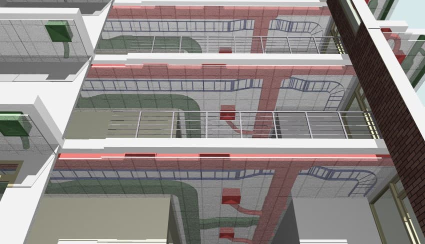
The ability to visualise MEP systems together with the whole building, in the same working environment, greatly improves communication between architects, engineers, planners and clients. Visualisation can be achieved in ARCHICAD with different colours identifying the different plant networks together with the wire building visualisation. ARCHICAD's powerful rendering tools also allow photo-realistic representations of the installations depending on the purpose.
For more information on the possibilities of simplifying relationships with other disciplines, including plant engineering, see the GRAPHISOFT OPEN BIM section.
0
0