DOGHE VMZINC® - Вентилируемая фасадная система
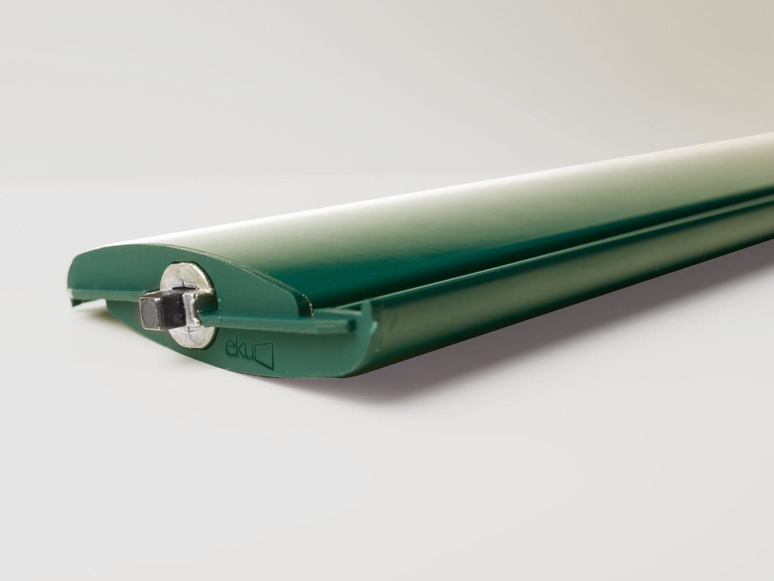
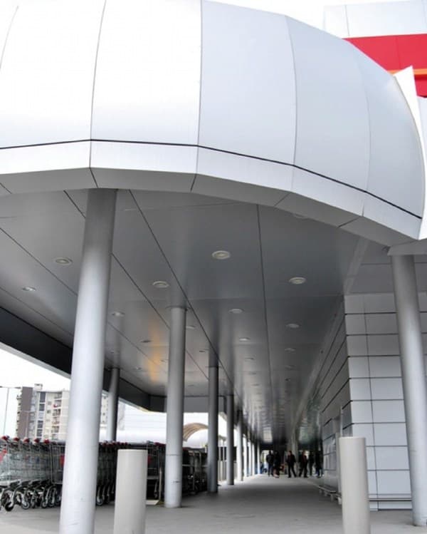
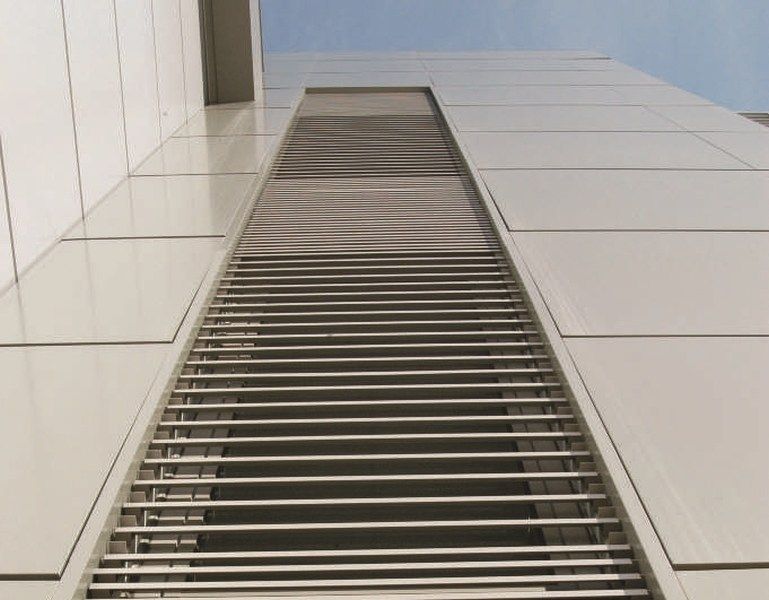
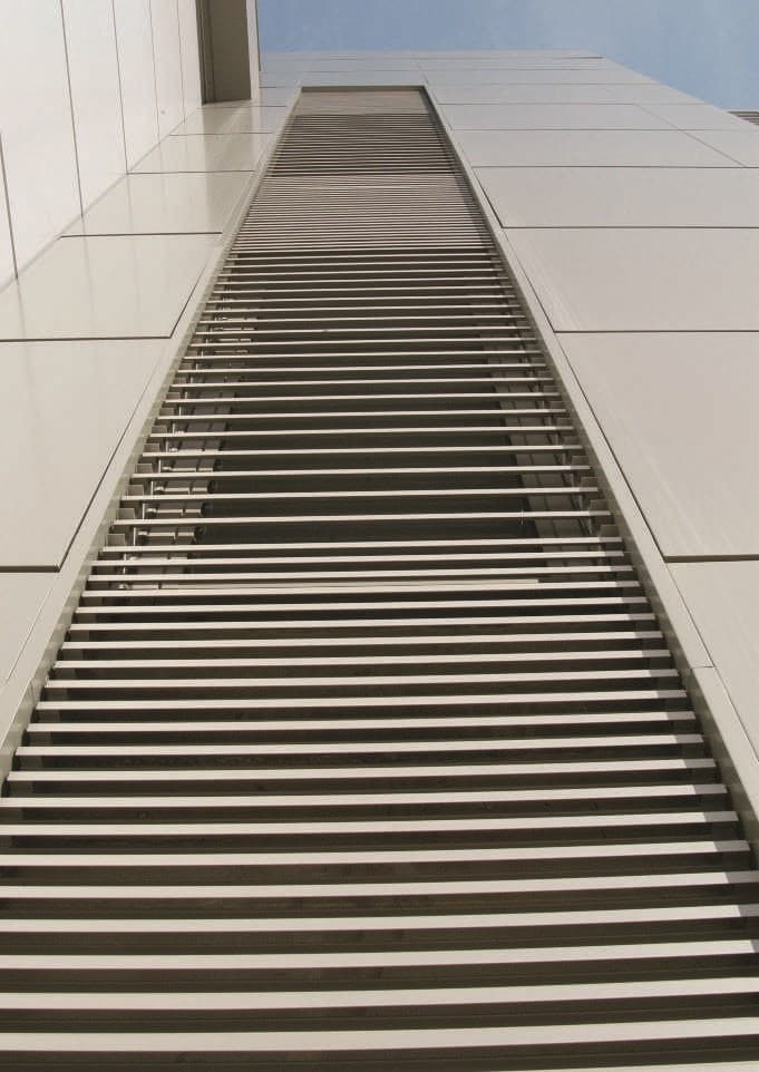
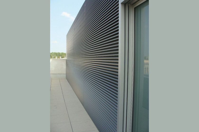
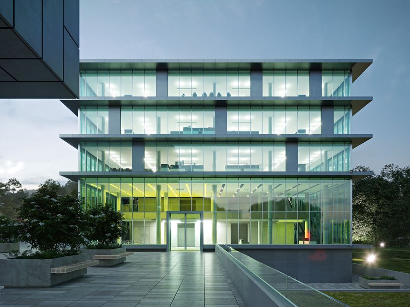
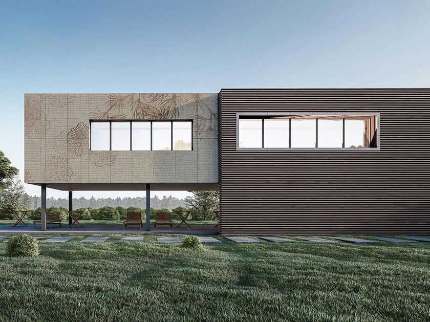
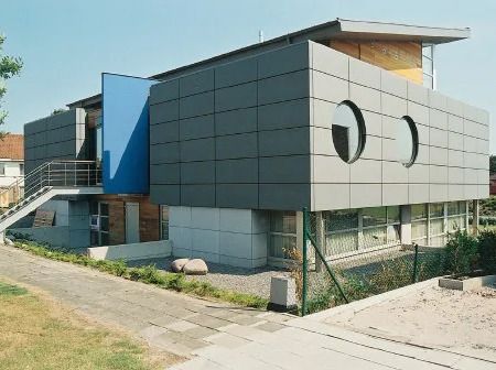
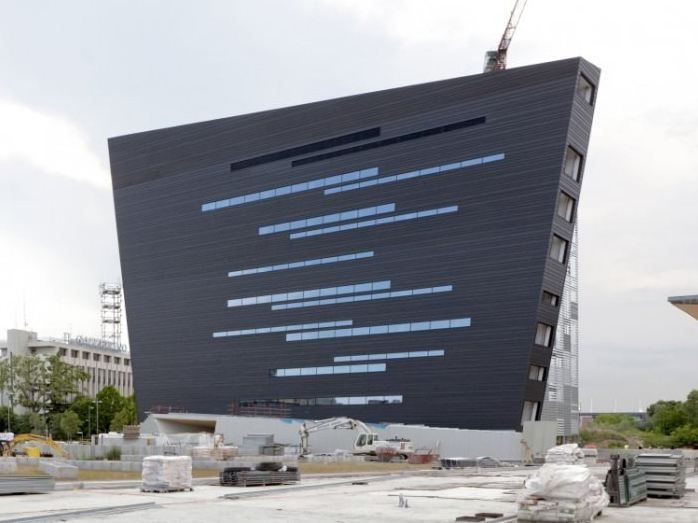
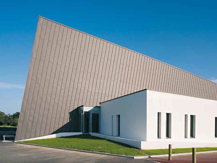
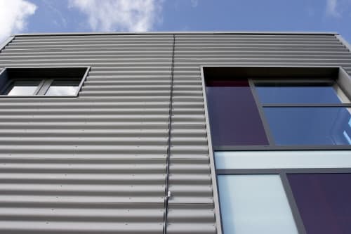
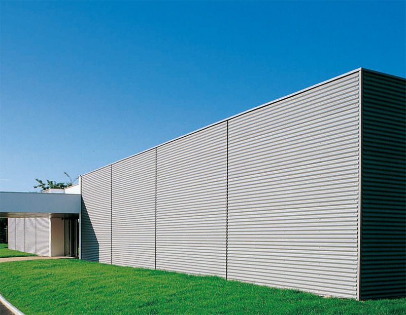
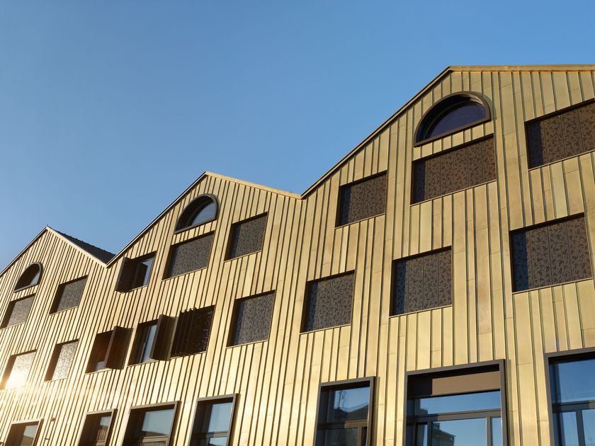
The slatted profile fa çade system is a ventilated façade system made of VMZINC® using DOGHE VMZINC® profiles with interlocking joints on a metal or timber substructure, anchored to the load-bearing structure, curtain walling or primary steelwork.
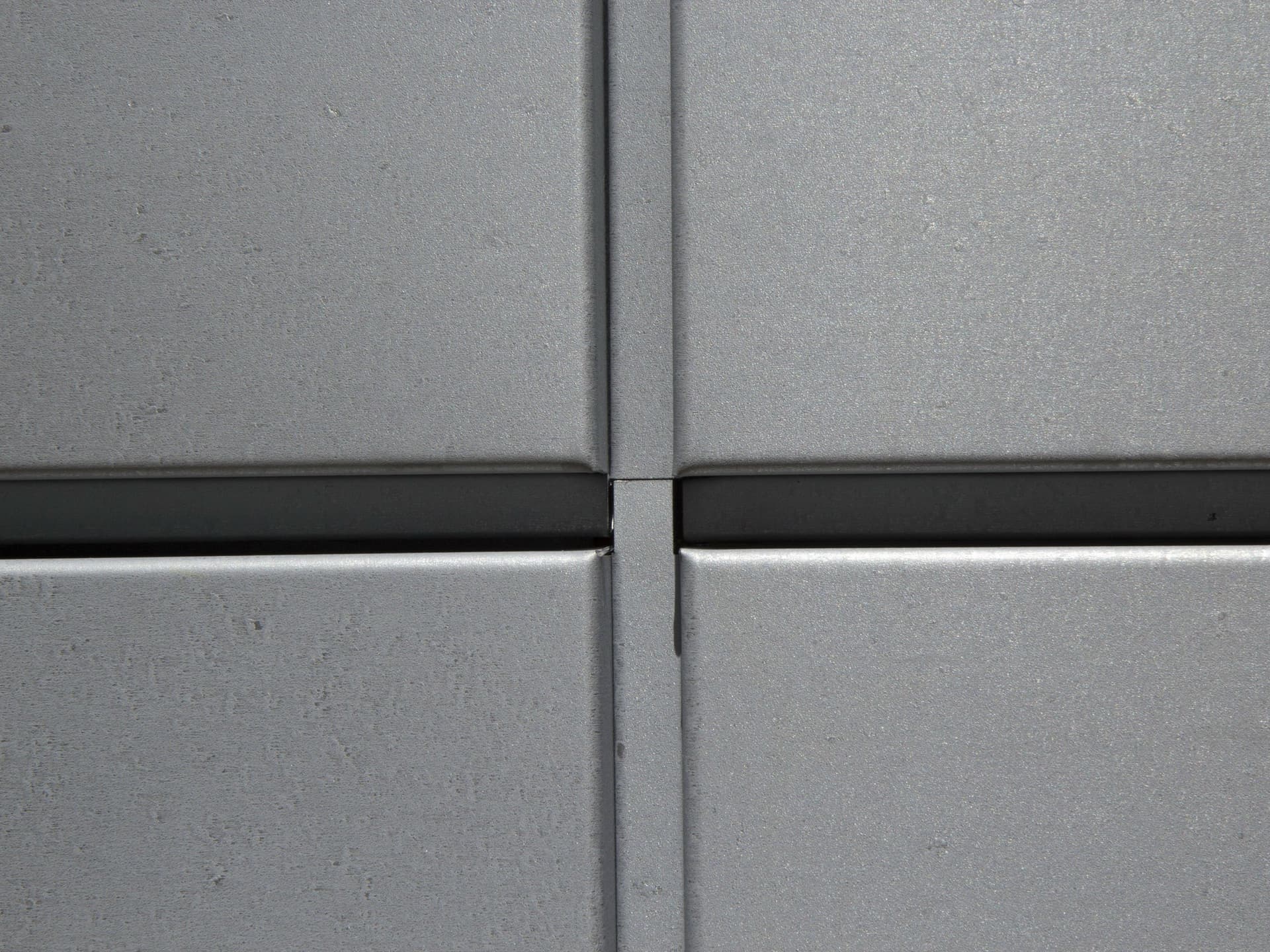
The profiles are assembled with each other by means of a tongue-and-groove joint with concealed fastening. They are anchored to the substructure by means of special stainless steel VM ZINC® clips.
The system allows for thermal insulation and ventilation of the façade.
The slatted profiles are normally supplied with a protective film.
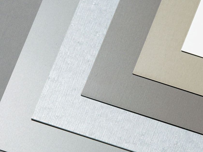
The staves are made of copper titanium zinc according to the European standard EN 988 and are available in the following finishes: NATURAL, QUARTZ-ZINC®, ANTHRA-ZINC®, BILACQUERED, PIGMENTO® and AZENGAR® in the four shades: Bark Brown, Lichen Green, Earth Red, Ash Blue.
Features
- Interlocking joint with concealed fixing
- Horizontal or vertical laying of the cladding
- Wide range of components offering solutions for any finish
- Patented stainless steel slide fixing to allow for thermal expansion of the profiles and ensure flatness
Uses
- Vertical facades and flat ceilings for office or residential buildings
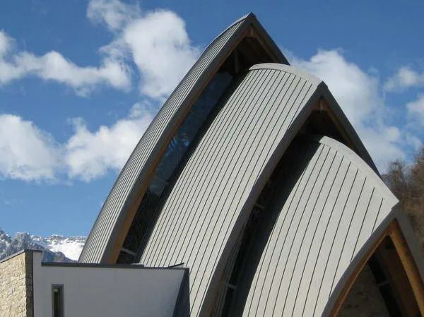
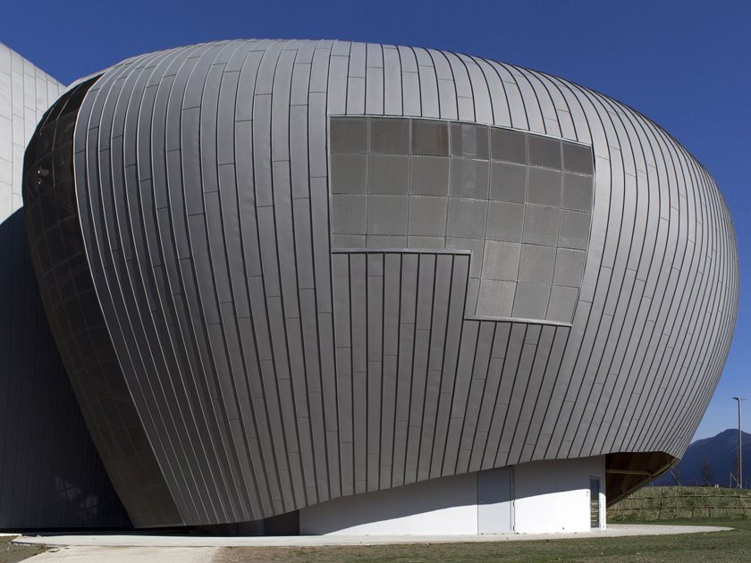
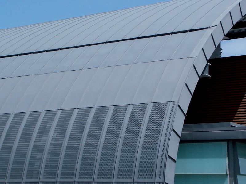
- Vertical barrel-vaulted façades (only staves in vertical installation)
- The system is used for both new buildings and renovations
Main features of the SLAB PROFILE
Dimensions
The profiles are available in three basic modules to allow for greater flexibility in layout and aesthetics. The module spacing is:
200 mm
250 mm
300 mm
The slatted profiles are available in project-dependent lengths from a minimum of 0.20 m to a maximum of 6 m.
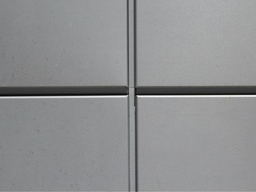
The joint width between two profiles can vary between 5 and 20 mm.
This dimension must be determined at the design stage and specified when ordering profiles.
Whatever value is chosen for the reveal, the module spacing of the profiles always remains the same (width of the flat element = module minus the width of the reveal).
Surface appearance
QUARTZ-ZINC® - ANTHRA-ZINC® NG - PIGMENTO® - AZENGAR®
Module spacing: 200 mm
Thickness: 1.00 mm
Length: 0.2 m≤ L ≤ 6 m
Joint width: between 5 mm and 20 mm
Profile height**: 24 mm
Weight(*) (kg/m²): 11.18
Module spacing: 250 mm
Thickness: 1.00 mm
Length: 0.2 m≤ L ≤ 6 m
Joint width: between 5 mm and 20 mm
Profile height**: 24 mm
Weight(*) (kg/m²): 10.40
Module spacing: 300 mm
Thickness: 1.00 mm
Length: 0.2 m≤ L ≤ 6 m
Joint width: between 5 mm and 20 mm
Profile height**: 24 mm
Weight(*) (kg/m²): 9.85
* system weight excluding substructure
** 24 mm standard, 8 mm (non-standard) and 35 mm (non-standard)
Design and Laying
LAYING DIRECTION
The profiles can be laid horizontally or vertically.
The choice of laying direction implies different aesthetic effects and technical finishing solutions.
When laid horizontally, the profiles are closed at both ends.
LAYING THESUBSTRUCTURE
Before laying, a diagram must be drawn to position the elements of the substructure and to accurately assess the dimensions of the profiles required: orientation, edge distance, width, length, width of joints.
Wood or metal substructures must be compatible with this system.
DOGHE VMZINC® provides a service to assist with the design and laying of the slatted system.
Accessories (supplied by VMZINC®)
A range of standard accessories has been developed for the main finishes:
Angle profiles for vertical and horizontal laying
Transverse joints for vertical and horizontal laying
Aperture coverings
Fixing tongues
For joints of 5 to 20 mm, they allow the profiles to be fixed to the substructure.
These tongues allow free expansion of the VMZINCR profiles the fixed points are determined according to the orientation of the profiles.
Angles
Angle profiles can be used for both horizontal and vertical laying. They are available in the same length as the slatted profiles.
Sliding inner corner and horizontal outer corner fittings can only be used for horizontal laying.
Horizontal outer corners are available in the same spacing as the profiles.
Joints
A flat vertical profile is used for horizontal profiles.
A continuous transverse joint is used for vertical profiles.
Note: The same component is used for lintel cladding or lower part finishes.
APPLICATION OF THE DOGGED PROFILE
TYPES OF FACADE
Vertical flat facade.
CLIMATE
Any region.
CLIMATIC CONSTRAINTS
The system can be used:
in lowland areas (maximum length 6 m)
in mountain regions with large temperature variations (maximum length 4 m)
Please refer to the table below for the permissible wind depression resistance for the slatted profile system.
If the height of the construction exceeds 30 m, please consult us.
COVERING AND CEILING
The system can be used on flat and vertical façades. It can be installed in false ceilings with a spacing of 200 mm or 250 mm, a maximum panel length of 3 m and fixing spacings of 400 mm max. The façades can be continuous or with openings.
Supporting structure
The new or existing supporting structure can be made of reinforced concrete, brick, metal or wood.
Substructure
The supporting substructure can be metal (galvanised steel, aluminium) or timber (refer to current regulations).
PERFORMANCE - DOGGED PROFILE
FIRE RESISTANCE
Refer to current regulations regarding any restrictions on the use of timber framing in particularly high buildings.
The fire resistance classification depends on the combustible mass of the wall itself (structure, insulation, etc.).
MECHANICAL STRENGTH OF THE DOGGED PROFILE (daN/sqm)
In order to offer greater resistance to the mechanical stresses that may occur in certain parts of the building (ends, edges, very tall buildings), it is recommended to use specially shaped profiles with a thickness of 1mm or to reduce the spacing between substructure elements.
Permissible resistance: Breaking point at γ = 15 (γ = safety factor)
Once the characteristics of the system have been established, it must be checked whether:
Admissible resistance > Stress due to wind tradition.
The stresses due to wind will be calculated by the façade contractor, taking into account the project site and UNI ENV 1951-2-4, Eurocode 1, Basis for calculations and actions on structures.
0
0