Управление строительствомATH ITALIA software#ATH ITALIA software#AUTOFLUID#Software#Thermotechnics and building services#Calculation of summer air-conditioning systems
AUTOFLUID - AutoCOUPE - СЕКЦИИ
AUTOCOUPE: How to draw sections quickly
Speed up the design and installation of duct and pipe networks: easy to create sections with AUTOCOUPE.
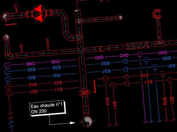
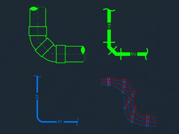
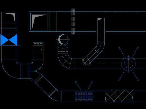
Generate cross sections from a 2D network created with AUTOFLUID
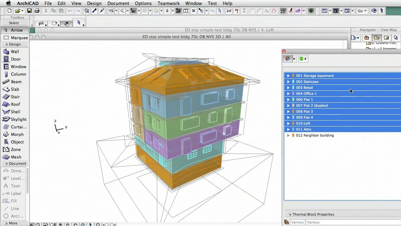
Control the choice of architectural environment.
AUTOCOUPE is still a work in progress. While waiting for the final version, the software can sometimes generate partial sections, which can be easily completed with the 'fitting' commands.
Fast and accurate sections with AUTOCOUPE
AUTOCOUPE automatically draws cross-sections from a plan view
Once the plan view has been selected, you can indicate where you want to draw the section directly on the drawing, regardless of whether the selected UCS corresponds to the plan view or not.
It is also possible to preview the section before validation. It is also possible to integrate architectural elements.
If required, the intelligent commands that allow you to complete the section where you need it, thanks to AUTOFLUID, make it very easy to do so with automatic channel recognition.
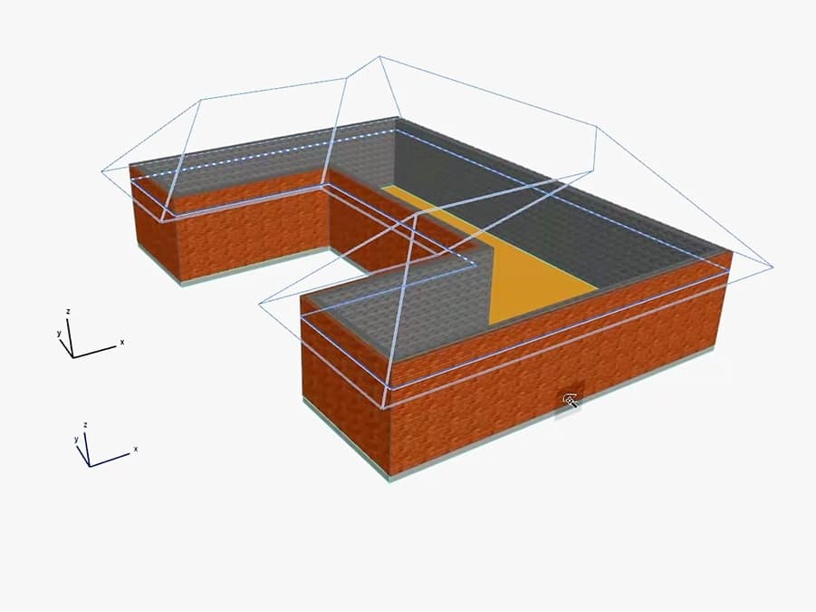
Section location and architectural environment
Choose a name (configurable) and position the cutting line in 3 clicks. This automatically selects all layer information.
Cross-sections can be adapted by changing the thickness and levels of slabs, ceilings and raised floors when necessary.
To customise cross-sections, remember to select only those architectural elements that you wish to appear in the drawing.
Autofluid is a new tool for the design and calculation of HVAC systems intended for thermotechnical professionals operating in the air conditioning, heating and cooling, hydro-sanitary (adduction and exhaust) and medical gases sector.
26
0