Управление строительствомATH ITALIA software#ATH ITALIA software#AUTOFLUID#Software#Thermotechnics and building services#Calculation of summer air-conditioning systems
AUTOFLUID - AUTOTUBE - Сети отопления
Speed up the design and installation of heating networks with AUTOTUBE. easy with AUTOTUBE.
Calculation, drawing and material list, with one- and two-wire graphic representation:
Piping
Valves and accessories
Work on actual dimensions according to type, PN and material.
AUTOTUBE's intelligent network routing process adapts the drawing to the network being drawn. The application intuitively suggests the most relevant design options, making it quicker and easier to use. Objects are proposed on demand as you proceed with the design, eliminating the need for time-consuming searches in the component library. There is never a shortage of object suggestions to design the network as consistently as possible.
Main functions:
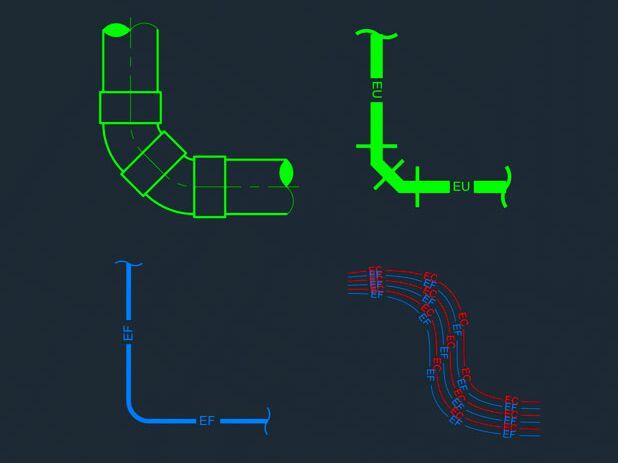
Point-to-point construction of pipe networks, in single- or two-wire mode, according to design specifications
Standard databases for heating and air conditioning networks: steel, copper, PVC, etc.
Possibility of creating new pipe catalogues
Automatic insertion of components: tees, branches, elbows, reductions, etc.
Insertion of fittings and branches into linear sections
Modifying the design of networks in 2D without redesigning them
Modifications to a descending curve, on a stretch already drawn, for example, are even quicker than during the initial drawing. On a course already drawn, the "Change" command allows you to replace one object with another very easily, thanks to a very intuitive command for a different selection, which takes into account the network already drawn. It is possible to replace by superimposing the new and eliminating the old, with a single command, without having to redraw the net.
It is also possible to move an object without redrawing it, as the connecting elements adapt automatically.
When an object is deleted, the network changes to adapt to the new configuration. Even if you delete a break, for example, the pipework automatically 'closes'.
Simplified text input
AUTOTUBE automatically adapts texts according to the drawing's dimension information. By clicking on an already drawn mesh, for example, some technical information (such as diameter) is recognised and retrieved.
The application inserts text prefixes and suffixes. Sections are formatted according to specifications.
These functions also include:
Creation of text on one or more lines
Automatic selection of the number of lines
Automatic drawing of reference lines, boxes, arrows, points, etc.
Adjustment of reference and frame size if the text changes
Choice of font and font size
Automatic adaptation to the drawing scale
Quick calculation of grids
AUTOTUBE has a range of calculation engines that meet the daily needs of HVAC system designers.
Calculation of the individual section of a pipe based on the flow rate (or power and dT) according to the type of fluid
Calculation of friction coefficients () for the proposed diameters
Dynamic calculation of schematic network dimensions
Automatic calculation of installation dimensions as the diameter is defined
And in addition, AUTOTUBE offers users the freedom to modify the result of calculations according to specific project requirements.
Dynamic preliminary diameter calculation
AUTOTUBE's 'Preliminary Calculation' commands use a visualisation that facilitates the calculation of diameters from the interactive network diagram. This diagram, which is clear and concise, contains all the information needed to draw the 2D plan of the network.
With this method, planning and drawing only takes place after the diameters have been indicated. This means that it is not necessary to design, calculate and then redesign the network based on the calculations obtained, as is the case with many 3D tools.
It is a powerful and lightweight tool: with a simple diagram, the calculation engine can be used to dimension any type of network.
To quickly calculate heating system networks
Draw a simple network diagram using the line command of your CAD software.
Enter the flow rates of the terminals.
AUTOTUBE immediately calculates the diameters of each section.
You get the dynamic dimensioning of the layout: you can change the values, try out new ones and immediately check the results, thanks to the calculation results that AUTOTUBE makes available immediately.
Working efficiently
If one analysed the experiences of working in plant design offices, one would discover that there are many margins and opportunities to simplify and speed up the whole process of design and production of technical drawings, mostly consisting of drawings, with a very high quality end result.
Here are some examples:
Representing the intersection of a two-wire or single-wire network by "hiding" or "cutting" one of the branches with just 2 clicks.
Retrieving dimensions from one plane to another
Automatic reconstruction of a pipe that has been cut
Operate on layers with ease: freeze, transfer or lock
Display dimensions and dimensions much more easily than with your CAD
Immediate scaling factors
Management of thicknesses, etc.
Clear and precise bill of materials
You can locate a specific area to perform a metric calculation
Automatic and immediate extraction of the pipe list in the defined zone
Automatic and immediate extraction of the list of equipment and miscellaneous components in the defined zone
Export of bills of materials from AUTOTUBE to AUTOCAD or EXCEL
Management and automatic insertion of attributes in blocks
Automatic drawing of wall layouts
Drawing of holes in walls or slabs
Creation of layouts with reference to drawn grids
Drawing arrangements without reference to the grids
Choice of preset shape
Automatic dimensioning of the arrangement
Numerical identification of the hole and automatic increment of the identification number
Automatic updating of the preset drawing label
Automatic list of hole patterns with export to AUTOCAD or EXCEL.
Exceptionally clear layouts of heating system networks
Layout of drawings and creation of nomenclatures are automatic and immediate:
Automatic insertion of formats and csrtyles
Creation of views with automatic scaling
Quick insertion of bills of materials
Simplified modification of scale in the various views
Automatic insertion in the title block of the file name, storage path and list of XREFs associated with the file
Arrows
Vertical ducts:
Automatic drawing and positioning of arrows indicating floor penetrations and flow direction.
Automatic change of arrow orientation
Horizontal ducts
Horizontal pipelines:
Indication of fluid direction
Indication of gradients
Management of dedicated layers.
Full parameterisation for maximum design speed
The original AUTOTUBE settings have been refined over the evolution of the application, based on years of experience. However, each user, in each office, operates differently, due to their own specific experience. Therefore, in order to ensure maximum productivity, the application can be configured in a very personal way.
For example:
Recognition of the preferences of the .DWG file, which, when opened, automatically loads them from the last changes
Setting the drawing scale
Setting layer names and colours
Setting the configuration of the various line types
Setting hatches for layer symbols (insulation, etc.)
Possibility of automatically adjusting scales and managing transformations between object space and paper space (automation possible, but not mandatory)
Possibility of setting drawing and calculation units of measurement
Possibility to adjust and adapt graphical aspects.
And much more ...
Easy and safe processing of background plans to work on
Entity colours
Level dimension colours
Z-coordinate resetting
Isolation of text, hatching, dimensioning, etc.
Font management
Ability to rename layers intelligently, to order them
Management of measurement system (metric/anglosaxon)
Management of line thicknesses, scales, etc.
Layer management
Thanks to the great flexibility in managing project layers, all names and structures are possible; with AUTOTUBE, their management is simple and optimised:
By type of network, according to single- or two-wire representation mode, always in a very flexible manner.
By type of graphic entity (networks, equipment, accessories, etc.).
Graphical variables
Each designer/planner has his own way of working, which is always the result of his own experience gained in the field. To facilitate this operability, AUTOTUBE allows you to adjust
The graphic representation of the appearance of the pipes of the various networks.
The representation of the texts, their dimensions, directional arrows and intersections of the pipe networks.
The management of proportionality, based on the output scale, also improves the readability of the work. For example. They are adjusted:
The diameters of vertical pipes
The line thicknesses
The dimensions of arrows
The dimensions of heating bodies
And many other graphic elements.
Calculation variables
To speed up and customise calculations, it is possible to modify certain variables, such as:
Material roughness coefficients
Flow rate and pressure drop units.
Autofluid is a new tool for the design and calculation of HVAC systems intended for thermotechnical professionals operating in the air conditioning, heating and cooling, hydro-sanitary (adduction and exhaust) and medical gases sector.
0
0