Управление строительствомATH ITALIA software#ATH ITALIA software#AUTOFLUID#Software#Thermotechnics and building services#Calculation of summer air-conditioning systems
ATH ITALIA software
Calculation of pressure drops in duct and pipe networks (heating, cooling and plumbing systems)
Directly with the CAD used for drawing, compatible with AUTOFLUID: AUTOCAD, BRICSCAD, ZWCAD
With minimum effort and maximum productivity
Calculation of pressure drops
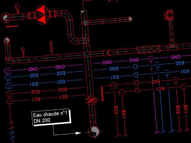
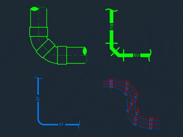
Components drawn along networks, in the AUTOGAINE and/or AUTOTUBE modules, already have a lot of information at the time of their creation. DZETACAD inserts the missing information to enable the calculations: length of vertical sections, flow rates, flow direction, etc.
It is thus possible to calculate pressure drops very simply: just select a section of the route. Dzetacad processes the calculation for the selected section and provides a report in Excel, ready for printing. It will contain both occasional and continuous pressure drops.
The tables and calculation formulas are taken from the main manuals used in the sector. The references of these texts are punctually cited in the reports.
Calculation of friction coefficients
The calculations, which take into account the layout of the network, are based on the COLEBROOK formula and consider
Material roughness coefficients
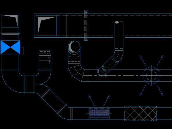
Duct shape
Altimetry and hygrometry for aeraulic network calculations
Fluid temperature
Calculation of occasional coefficients (zeta)
Tables and calculation procedures based on industry standard studies
User information on the calculation method used
Takes into account the fluid direction (supply, return)
Determination of ZETA coefficient and relative pressure drops based on component design
The ZETA coefficient can be forced for special components.
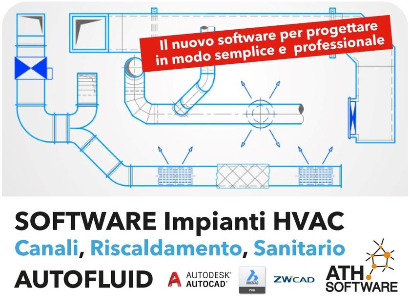
Autofluid is a new tool for the design and calculation of HVAC systems intended for thermotechnical professionals operating in the air conditioning, heating and cooling, hydro-sanitary (adduction and exhaust) and medical gases sector.
0
0