Управление строительствомCDM Dolmen#CDM Dolmen#Software#Structural calculations#Structural calculations for steel#Construction
CDM Dolmen
DOLMEN ACCIAIO is a structural calculation programme dedicated to the design of steel structures.
DOLMEN ACCIAIO performs a static analysis, a simplified seismic analysis and a dynamic modal analysis, it carries out the verification of members, and the verification and design of structural nodes and structural steelwork as a whole; a dedicated CAD produces the construction site drawings.
Steel Calculation
The modules relating to steel structures constitute one of the major sections of the DOLMEN programme and are as follows:
Verification of steel rods
User sections
Profile list
Frame drawing
Node verification
Steel structures, while being less difficult to calculate than reinforced concrete, present an infinite number of executive variations. DOLMEN makes it possible to verify steel beams and plates using both the limit state method (calculation at the elastic limit) and the admissible stress method (to maintain compatibility with older standards), and to calculate the most typical connections thanks to a library of nodes that has been increased from version to version.
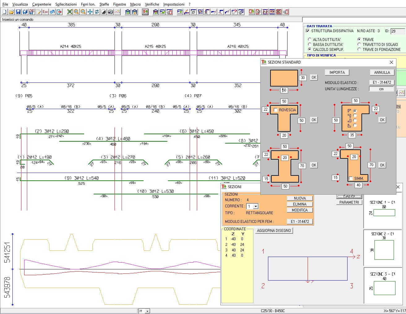
In Rods Verification it is possible to use sections with a standard shape (rectangular, L-shaped, T-shaped, etc.), or sections taken from a large profile library, or even sections created by the user by drawing or by aggregation of existing profiles. By means of a specially dedicated module, User Sections, inertial properties and shear and torsion coefficients at significant points are, in fact, automatically determined.
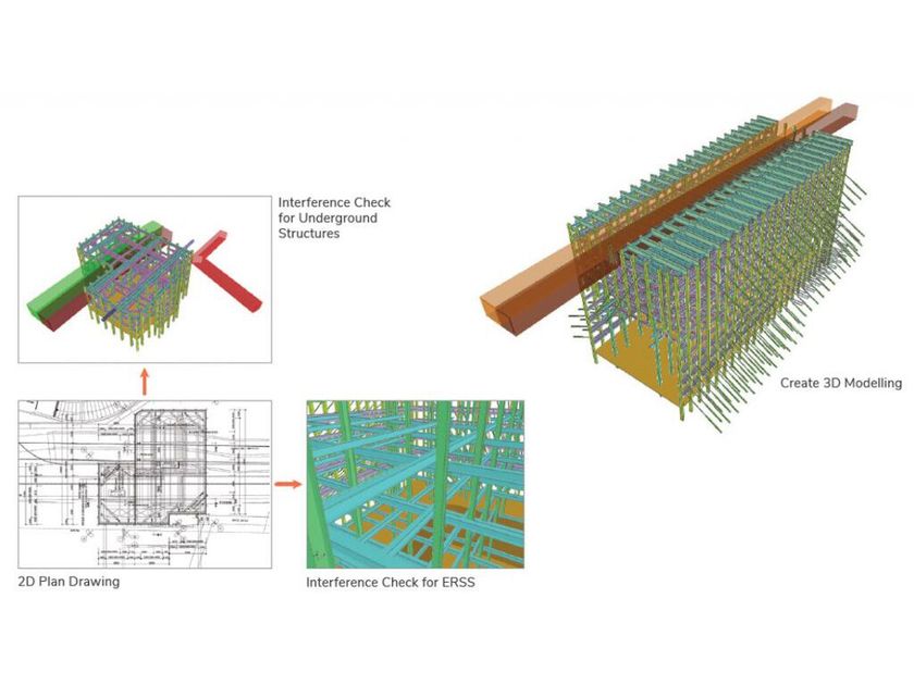
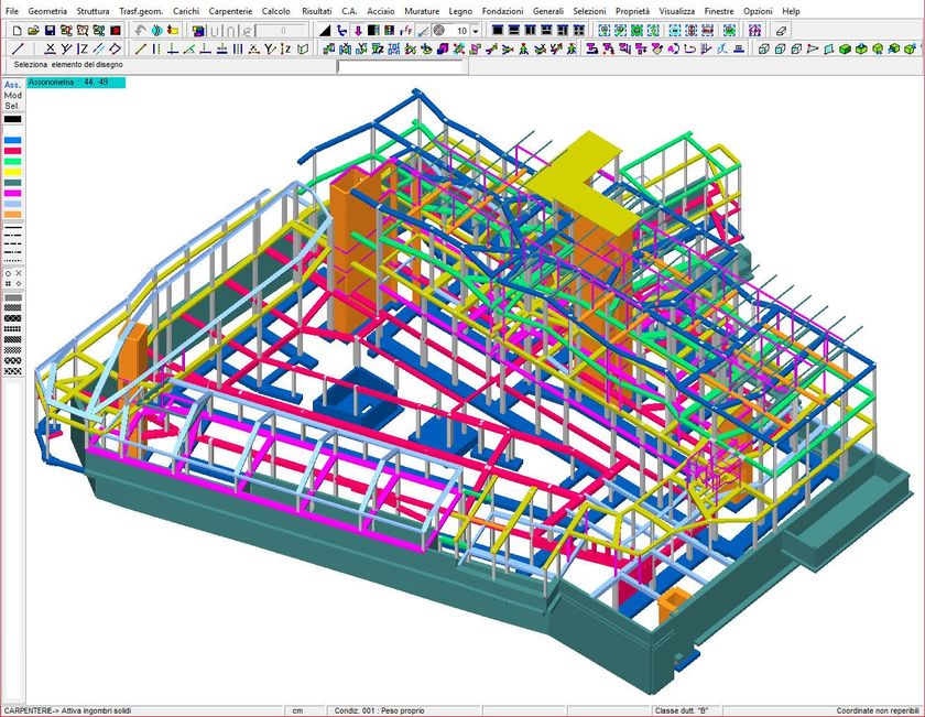
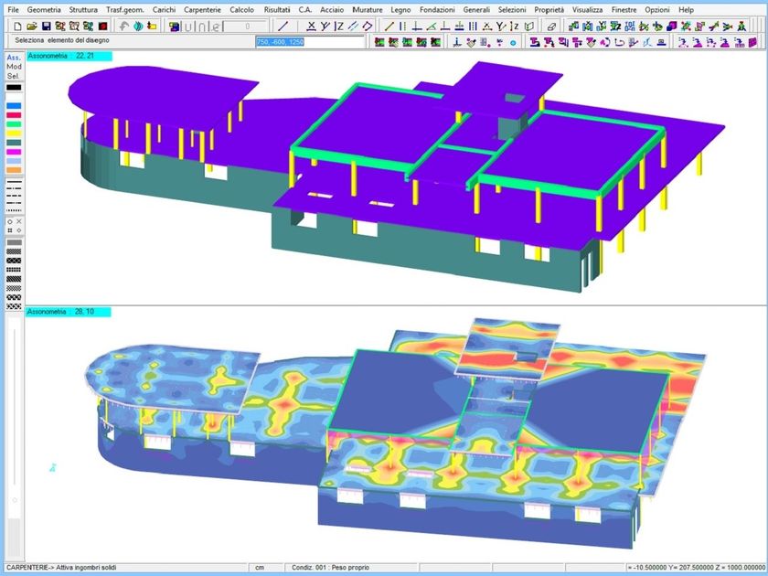
Starting from the three-dimensional model of the structure, created in the 3D CAD Structure, it is possible to make a selection of the members to be checked according to many parameters: material, colour, type of section, type of profile, etc.
The selection criteria can also be stored and used again in case of updates applied.
Verifications are carried out according to NTC 2018 and CNR10011/1985 and in compliance with Ord. 3431/2005 by calculating 6 stress components and performing global buckling checks of the member.
The report drawn up by Verification of members shows the worst stress sextet
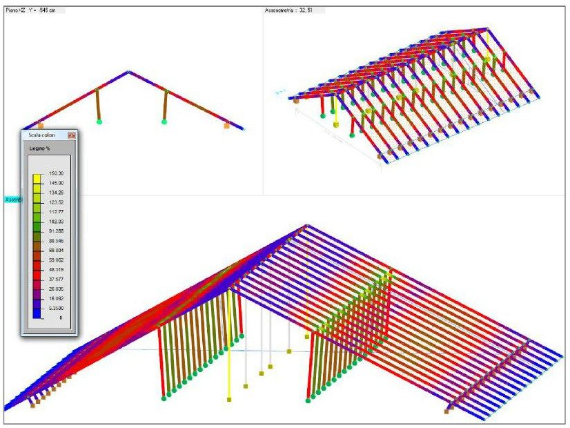
among those analysed and the stresses with an indication of the maximum for each component. The Rod Verification module makes it possible to have colour-mapped representations of sigma and tau stresses, ideal stresses, buckling stresses and percentage of utilisation in 3D CAD Structure.
DOLMEN was chosen for the structural calculation of scaffolding by PON CAD (produced by MEC CAD), a powerful graphic programme for the professional design of any type of scaffolding in 3D mode, which directly generates the structural model of the scaffolding in DOLMEN.
The Bill of Profiles module draws up a summary table of the parts present in the structure, classifying them by material, section and length; this graph can be exported in .dxf and in an Excel® readable format.
Finally, the Bill of Profiles allows you to carry out a calculation of the structure, highlighting the profiles involved, the weights, the surface that can be painted, etc.
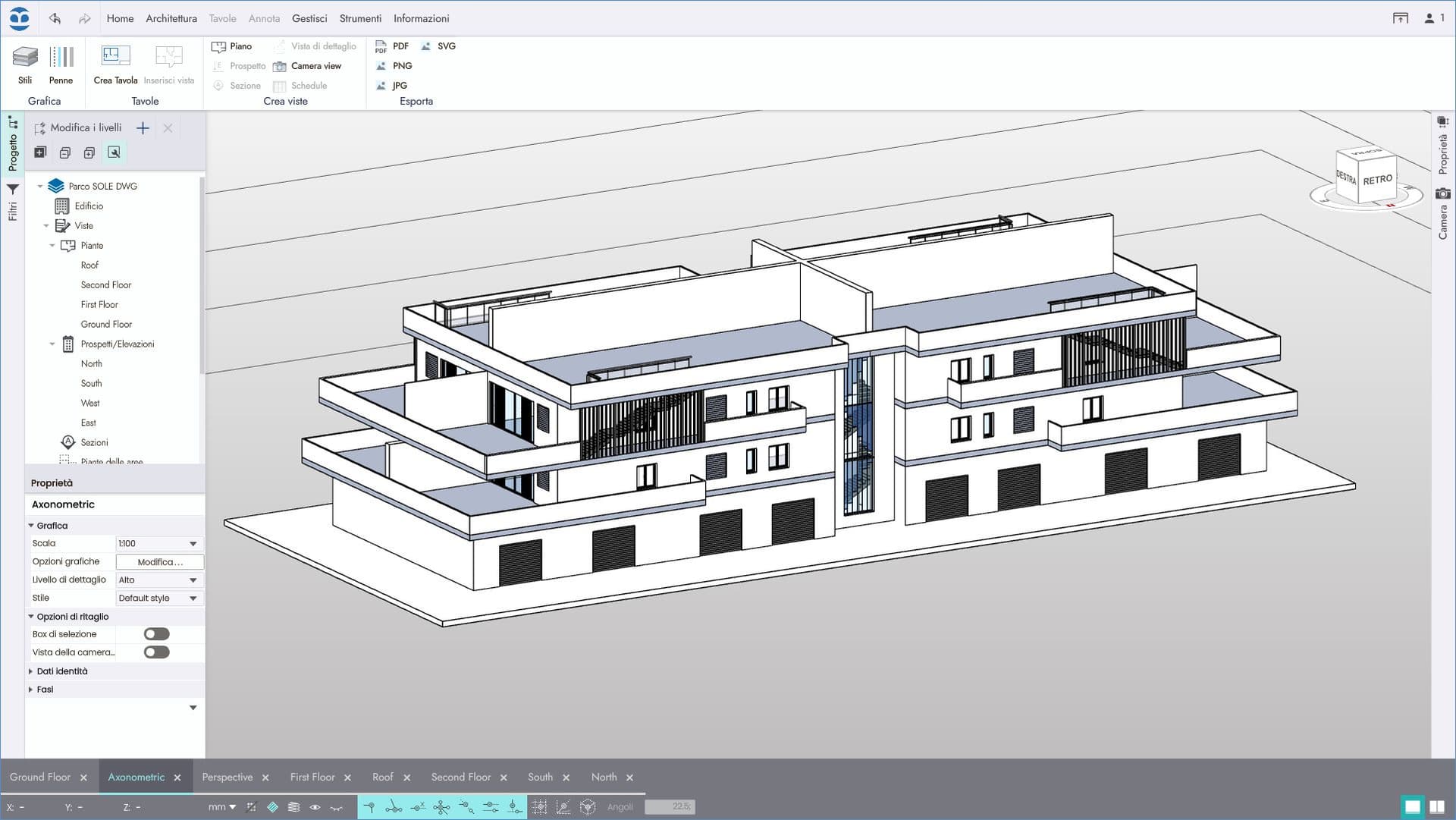
The Frame Design module draws the outline of the members belonging to a certain group (typically a flat frame). Here the dimensions of the various profiles are then represented with an indication of the section and number of each node, the latter is also shown in the connection tables in order to have an immediate comparison between general tables and connections.
Knot verification deals with numerous types of union:
Each module is dedicated to a specific type of knot and is only applicable to it in its entirety, but there is nothing to prevent the calculations or drawings from being used in a partial manner, in the case of knots that do not perfectly coincide with the proposed type.
The geometric definition of the knot is carried out by the user entering the dimensions of the connection elements (brackets, joint covers, plates, etc.) and the number, position and diameter of any bolts present. With regard to the sections of the rods converging in the node, it is possible to make a choice from the profile, or to import sections from the three-dimensional graphic environment, indicating which node of the structure the node being realised refers to. The same principle governs the acquisition of the acting stresses, which can be entered by the user or imported from the calculation phase, indicating from which nodes of the structure to import. In this way it is possible to verify all nodes corresponding to the type under examination in the structure at the same time. It is also possible to verify a node in the absence of a structural context.
An automatic function allows plates and other elements to be dimensioned on the basis of geometric contour parameters.
It is always possible to save the geometric data required to define a node, just as it is possible to draw on previously saved nodes to define new nodes. For all unions, an executive table is provided, in which the three dimensioned views and details of the connection elements are presented, which can be exported in .dxf, and the calculation report with the classic bolt shear checks, plate re-bending, etc.
Three-dimensional viewers are available for a better understanding of the dimensions of the different elements that make up the connection; they update automatically each time the data entered are modified.
0
0