Управление строительствомCDM Dolmen#CDM Dolmen#Software#Structural calculations#Finite element (FEM) structural resolvers#Construction
CDM Dolmen
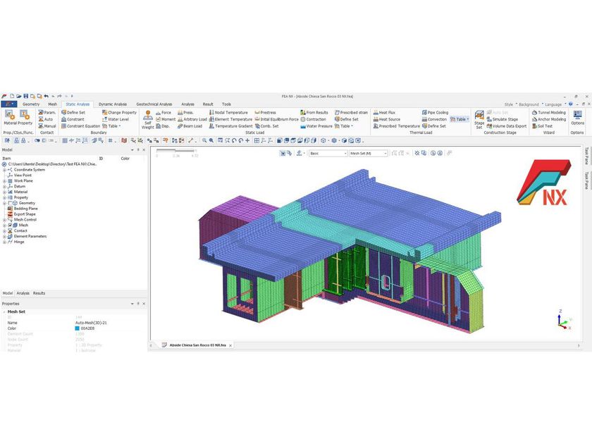
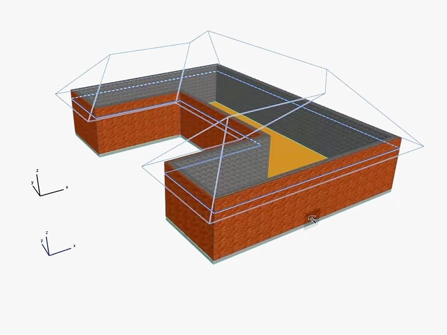
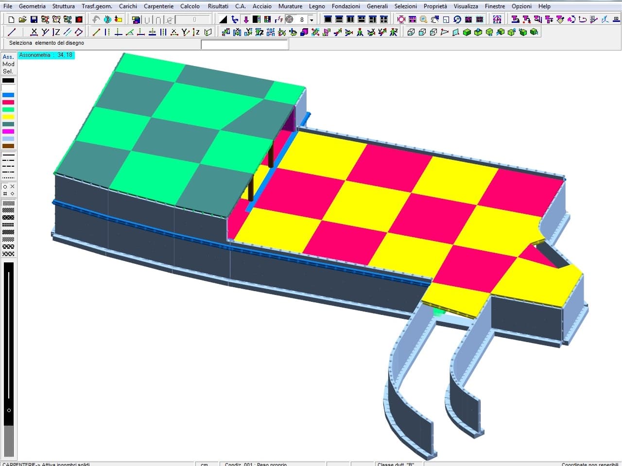
DOLMEN FEM E 3D is a finite element stress analysis software. It includes a three-dimensional modelling module that allows the structure to be defined by simply drawing it within a fully developed 3D CAD, such as the F.E.M. solver, within CDM Dolmen.
DOLMEN's three-dimensional graphic environment is supplemented by a set of additional functions that can be activated within it, which automatically and optimally generate a plane mesh consisting of shell elements of imposed dimensions.
Thesoftware
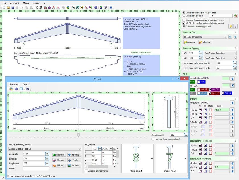
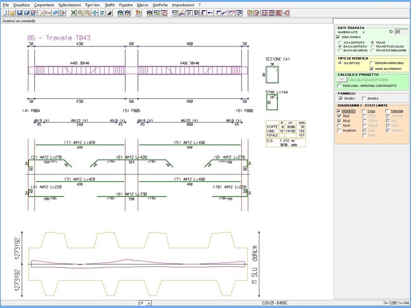
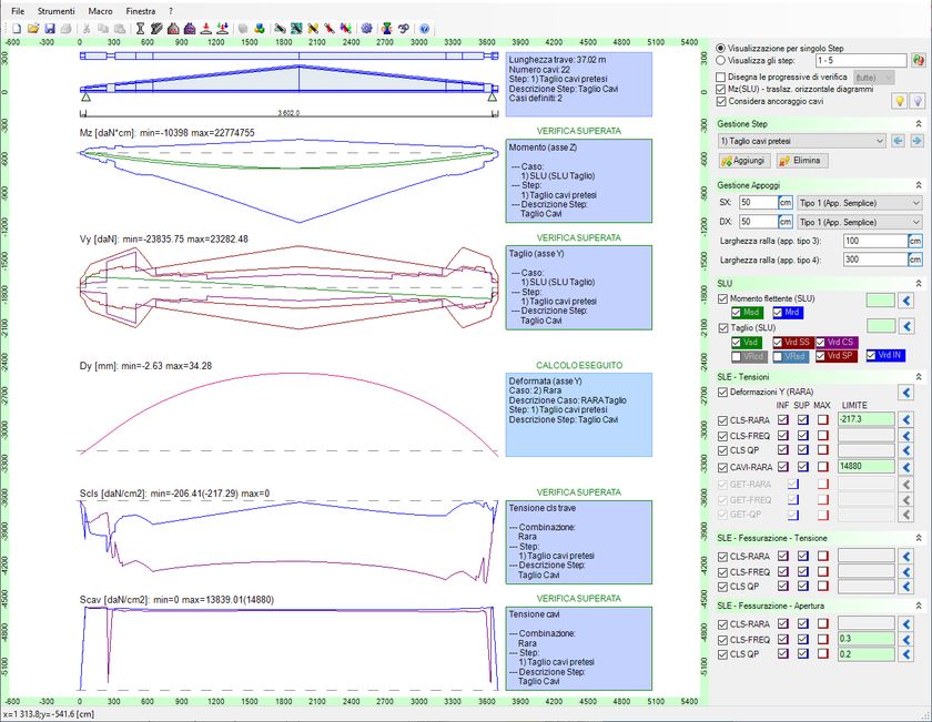
The Stress Analysis is carried out within DW1, the main interface and unifying element of the programme, in which the structural model is constructed, the load analysis is carried out, the results of the stress analysis are queried, and from which one passes seamlessly to the modules for the dimensioning and verification of construction elements in reinforced concrete, prestressed concrete, steel, load-bearing masonry or other materials.
The full adherence of the interface to Windows standards, together with the presence of a hypertextual and contextual help, accompanied by short animations for a quick explanation of the most complex commands, ensures that the user is quickly able to master the management of the structural model.
The structure is defined simply by drawing the finite element model, i.e. by drawing the uniform beam diagrams and covering these geometric elements with their physical properties (sections, joints, rigid ends, etc.), and using the appropriate functions to generate shell meshes.
In this process, the user has all the functions of a general-purpose 3D CAD at his disposal, plus functions specific to the creation of a structural model. This approach of generation by drawing the model allows any type of structure to be easily defined, even the most complex, without being constrained by work plans or the choice of specific structural types, and without limits on size (unrestricted version DW1A) and shape. However, it is always possible to import tables in ".dxf" format, the carpentry information of which can be used to plot the various structural elements. Alternatively, it is possible to use a three-dimensional dxf representing the static wire diagram to be covered within DOLMEN FEM E 3D with the structural properties, or it is also possible to use the functions in Dolmen Plan (DW4) for reading and automatically generating columns from a plan.
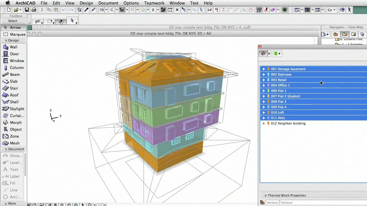
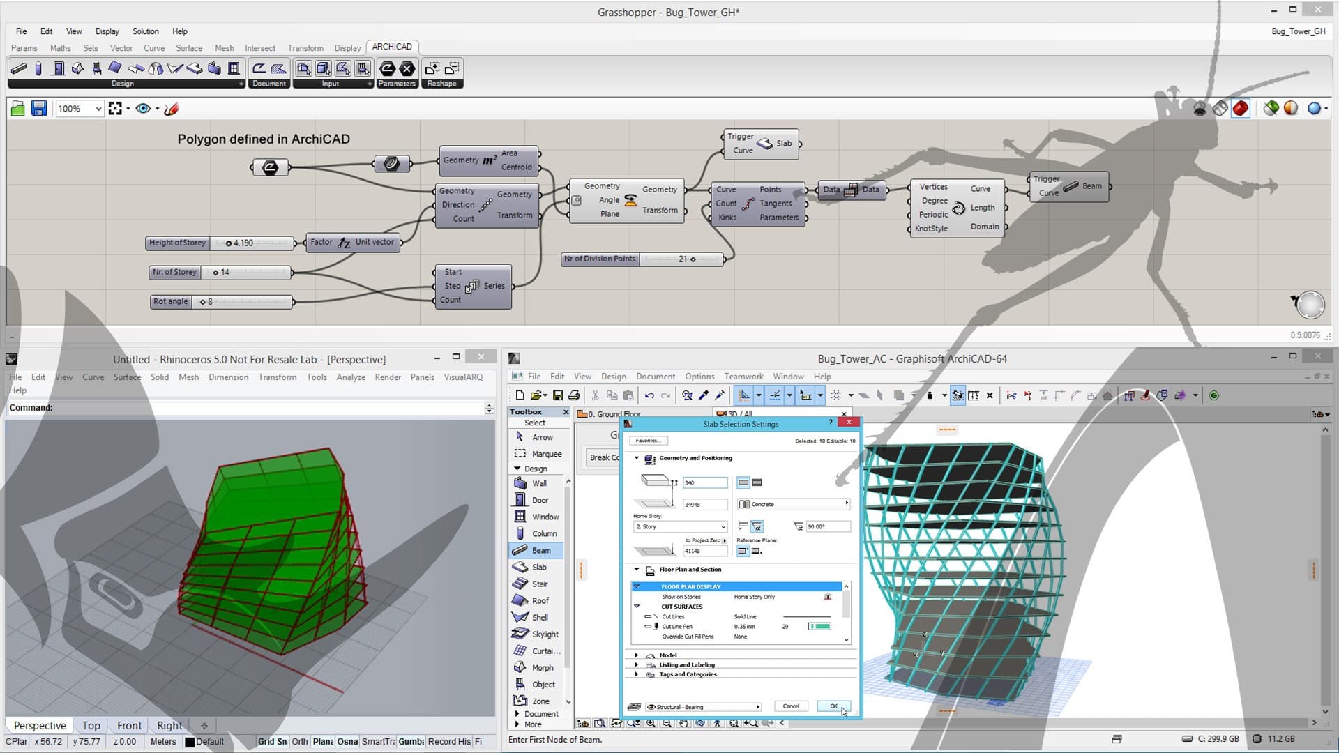
The structural model data can be saved in IFC format, which can be read directly by the most common architectural modelling software, such as ArchiCAD, Allplan, Revit, etc. DOLMEN is also able to import structural objects (beams, columns, plates or septa, walls) contained in the interchange file in IFC format into the 3D CAD Structure. The reinforcements calculated using the modules DW14 - Continuous Beam, DW16 - Columns and DW8 - Plates and septa can be exported in the IFC format, thus enabling both three-dimensional visualisation and calculation.
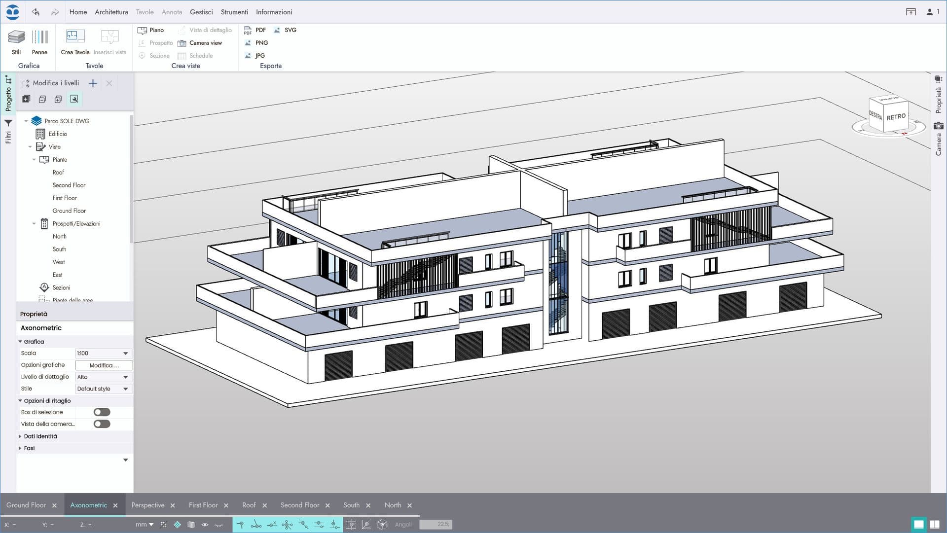
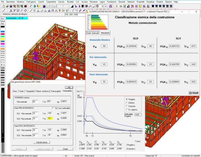
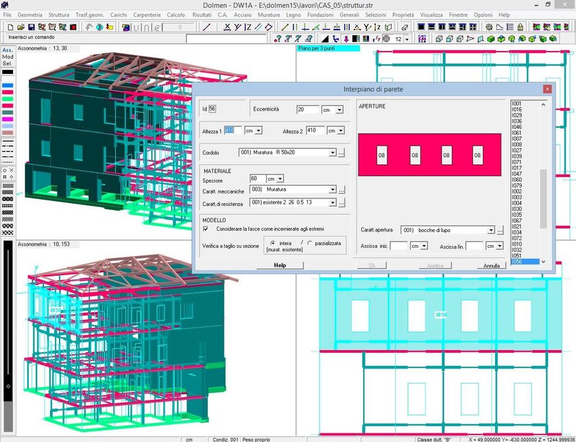
The main window is subdivided into parts, from one to four, each of which can contain a different view of the model (axonometry and sections on user-defined planes): it is possible to rotate the structure or see its details up close, to activate the display of the dimensions in the desired parts so as to explore every detail and have constant control over every change made.
Inside the CAD3D structure there are also diagnostic functions (the Check dataBase) that have the task of pointing out any possible modelling defects during the model creation phase.
The stress analysis is carried out by a native FEM solver: the extreme versatility and interactivity of the 3D CAD and its close integration with the FEM solver are guaranteed by the fact that both have been fully developed within CDM Dolmen.
The finite element solver allows the use of rod elements with 6 degrees of freedom per node (thus counting axial, shear, bending and torsion stresses) and 5 degrees of freedom shell elements with 3 or 4 nodes (coplanar, shear and bending stresses); both can be associated with a distributed elastic stiffness according to the Winkler model.
It is possible to decide the degree of reciprocal constraint between the individual rods by acting even partially on each of the 6 degrees of freedom, and to rotate each rod so that it assumes the correct position around its axis.
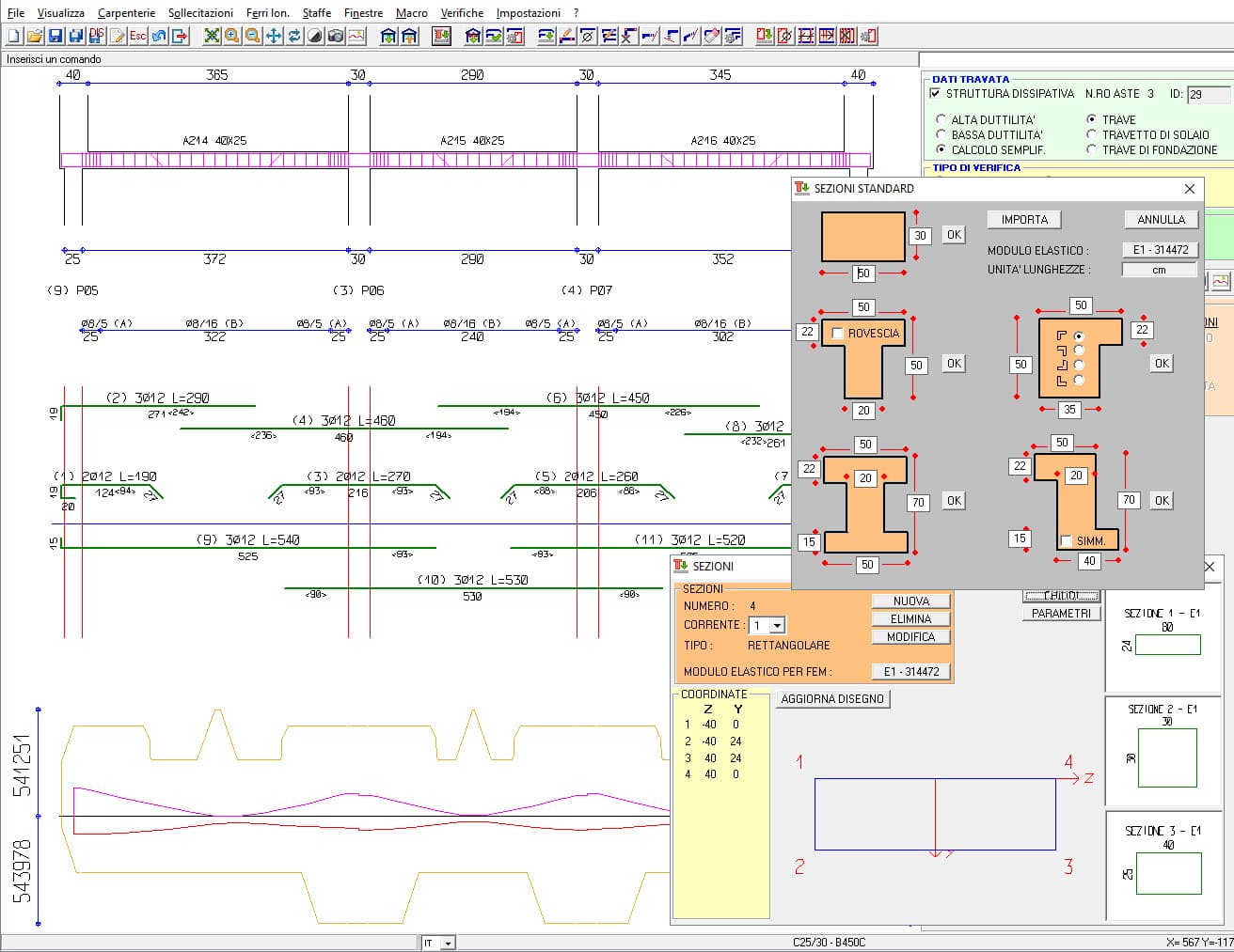
The programme provides various types of section, including an internal profile, as well as the possibility of using CAD-drawn sections.
Each node can be given a rigid or yielding constraint: classic constraints such as interlocking, hinge or support are proposed automatically and it is possible to define the elastic constraint corresponding to a plinth. The programme also allows the introduction of imposed displacements or the simulation of the case of a continuous Winkler-style foundation.
The construction of meshes is automatic, carried out by means of an automatic mesh builder (DW17), or can be obtained by combining simple quadrangular meshes.
Loads can be applied directly to structural elements (loads on nodes or concentrated, distributed or thermal loads on members and shells), or you can also have the programme calculate the contribution on individual elements of "load areas", "floor loads", "load lines", "linearly variable loads".
Seismic actions are created automatically on the basis of the various standards, including of course NTC 2018.
The solutions of each load condition are then combined by associating a different coefficient to each one to obtain the verification cases: the programme automatically proposes the coefficients and seismic masses relating to the combinations of S.L.U., S.L.E. and S.L.D. required by the various Standards, including the Technical Standards for Construction of 17/01/2018. Other combinations can however be generated by the user.
Dolmen Win allows static analysis and dynamic analysis. It is possible to insert rigid planes with a direct function or with the introduction of appropriate membranes in order to take into account particularities such as holes, non-infinitely rigid planes and irregular planes. The Dynamic Solver (DW6) allows you to perform a complete analysis or condense masses into a few nodes. Modal form control gives the possibility to interpret the behaviour of the structure under cyclic horizontal actions and to control design choices.
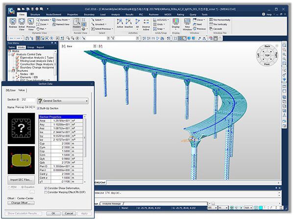
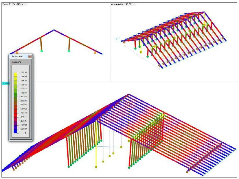
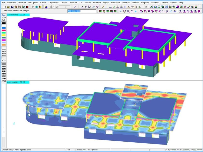
DOLMEN FEM E 3D also has a wide range of functions for querying and displaying the results provided by both the structural analysis and the individual verification modules: colour mappings, vector diagrams or animations (for deformations and vibration modes) are available; for all representations, a point-in-time query is possible.
Main functionalities
Data input
Direct data input, facilitated and in exclusively graphic form in three dimensions.
Indirect data input, via 2D DXF or 3D file generated by external CAD.
Up to four windows with plan or axonometric views can be opened simultaneously, which can be freely customised by the user.
Use of the intuitive concepts of effective primitives and construction lines.
Functions for "capturing" remarkable points such as: nodes, elements, grids, construction lines
Quick changes for groups of selected elements (colour, line type, windows, name, etc.) with the possibility of combining and filtering multiple selections.
The data imported from external CAD can be generic drawings on which to build the structure, or floor carpentry from which DOLMEN automatically reads the position and section of the columns.
Checking the structural model for possible inconsistencies.
Loads on nodes according to the 6 components, loads on members in local, global and projected reference systems.
Loads on uniform members, partials, trapezoids, concentrated torques and forces, thermal distortions, self-weight, seismic loads.
Area and floor loads, with search for bearing beam surfaces.
Stress analysis
Static (DW1) and dynamic seismic analysis with response spectrum and modal superposition (DW6).
Complete or simplified dynamic analysis with rigid planes (DW6).
Release of the 6 degrees of freedom at the ends of the beams, with any combination and percentage
Automatic generation of the mesh of the structure or parts of the structure.
Freely customisable section archive by the user.
Visualization of results
Three-dimensional graphic display of stress diagrams, deformations, eigenvectors, stresses and principal moments, with the possibility of generating colour maps of stresses and ground pressures.
Pointwise interrogation of structural elements for information on stress and deformation states.
Calculation of stresses in intermediate sections.
Three-dimensional animation of deformations of conditions and load cases.
0
0