Управление строительствомCDM Dolmen#CDM Dolmen#Software#Geotechnics and foundations#Foundation calculations (plinths, slabs, ground beams)#Pile and micropile calculations
CDM Dolmen
IS PLINTI is a software for the verification according to limit states and permissible stresses of superficial foundations (plinths on Winkler soil, isolated or in groups, on piles, connected by rectangular or inverted T beams), both from a structural and geotechnical point of view.
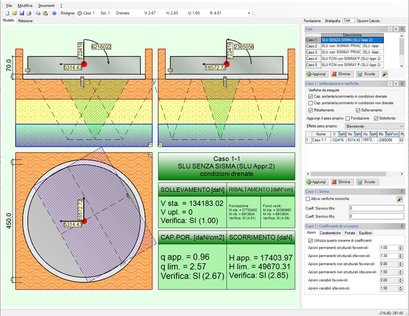
Once the plinth has been defined with its geometric and reinforcement characteristics, the abutment or socket, if present, has been chosen, and a stratigraphy and load cases have been associated, the programme verifies the load-bearing capacity, short- and long-term failures, shear and punching stresses, and calculates the stresses at the head of the piles.
Theanalysis of the socket is carried out in accordance with CNR 10025/84 standards.
The reinforcement tables, the general plan of the work and the individual plinths can be exported in .dxf and the complete calculation report shows the calculation results in detail and can be saved in various formats (.doc, .html and .txt).
PROPERTIES OF THE SOFTWARE
The input of data can be done either numerically, via shortcut tabs, or graphically via simple 'drag and drop'.
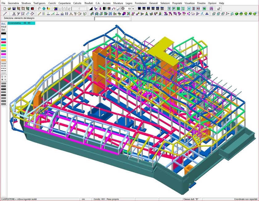
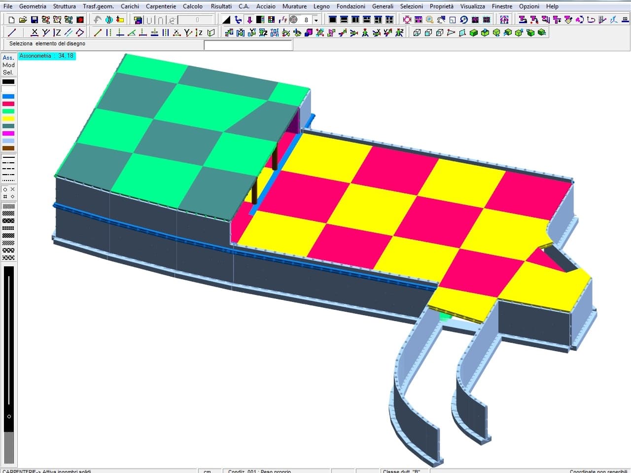
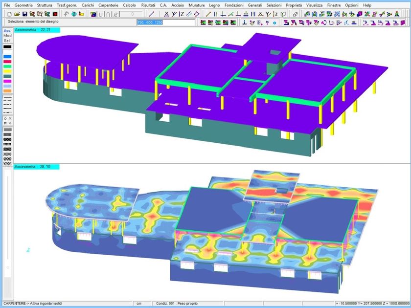
Alternatively, the foundation plan, plinth and column geometry, conditions and load cases can be imported from the graphic environment of Dolmen WIN.
The geometric shapes of plinths that can be analysed with IS PLINTI are varied, and a distinction is also made between the presence of reinforced and unreinforced magrons; depending on this choice, the pressures on the ground will be calculated at the end of the magron, in the first case, otherwise the area resulting from the 45° punching of the magron is considered.
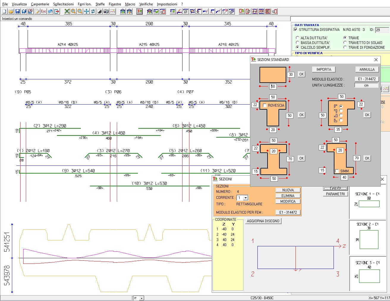
It is possible to define a priori a typical reinforcement scheme for the plinths and connection beams (verified in the earthquake). A reinforcement scheme is assumed to be suitable for the plinths under examination; the various parameters of the reinforcement, the type of upper and lower reinforcement, the diameters of the reinforcement bars, the concrete cover, the maximum and minimum pitch, and the reinforcement distribution methodology are defined. A complete check of the data is carried out prior to the analysis and any inconsistencies are reported. For the verification of the foundation in IS PLINTI, a reinforcement is set and, after the calculation has been carried out, it is checked whether it is present in sufficient quantity and whether the verifications required by the standards are exceeded. If this is not the case, any deficiencies will be reported and the plinth and its reinforcement will have to be redesigned.
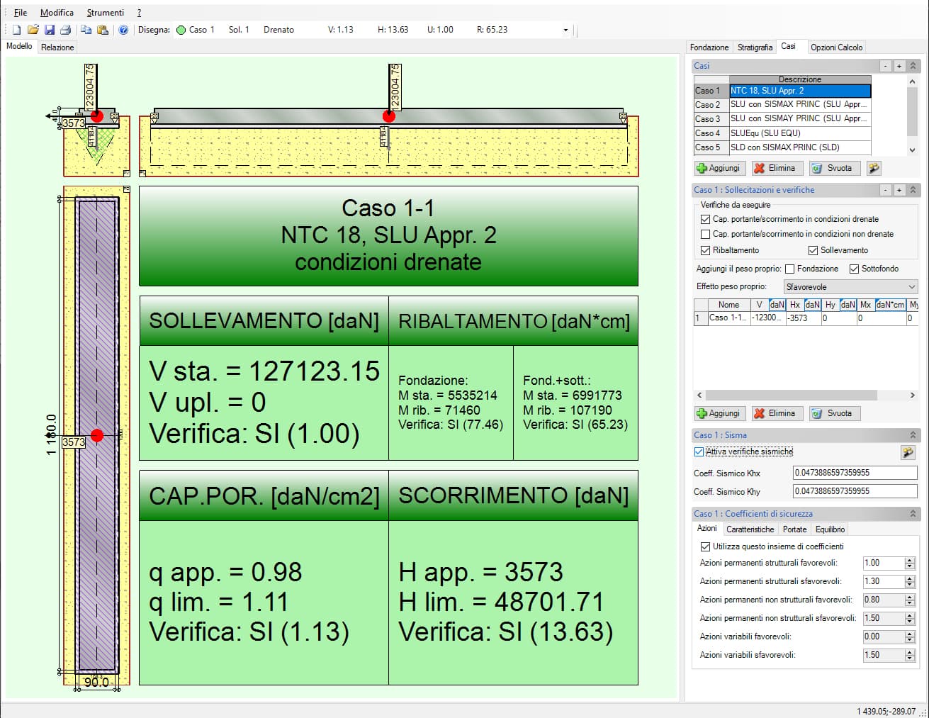
The results provided relate to:
verification of load-bearing capacity
verification of short and long term failures;
verification of sliding;
calculation of stresses acting on the magron (with neutral axis);
calculation of stresses acting on the soil;
flexural, shear and punching verification of the plinth;
flexural verification of the reinforced magron;
verification of the socket according to CNR 10025/84 standard;
verification of connection beams (seismic verification);
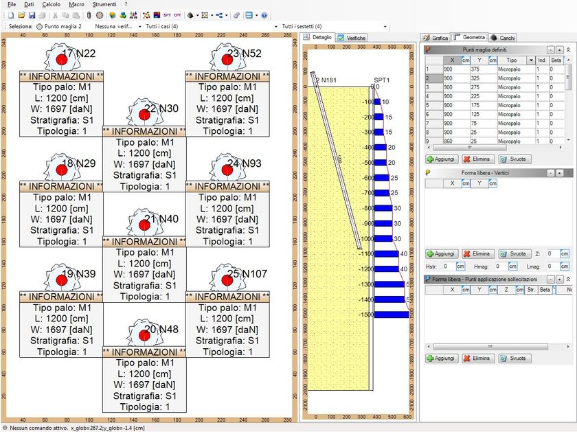
calculation of stresses at the head of the piles.
It is possible to define square, rectangular and circular piles, having any position with respect to the plan of the plinth.
The barycentres of the piles are considered points of application of the load.
The presence of the socket can be considered, verifying it according to CNR 10025/84 standards.
It is possible to define circular reinforced concrete piles, underneath the plinth, giving the main characteristics of the geometry and reinforcement.
When the analysis has been carried out, the stresses acting on the head of each one, calculated on the assumption of a perfectly rigid connection plate, are displayed. Exporting a plinth on piles into the IS PLINTI programme actually calculates and passes on the maximum stresses acting on the piles of that plinth. At this point it is only necessary to define the soil and the methods for calculating lateral and base loads.
Different load conditions are distinguished, consisting of vertical load, horizontal load and bending moment.
The conditions grouped and analysed give the load combinations, for each of which verifications are performed. The stresses acting on the plinth can be obtained directly from the analysis carried out by Dolmen Win.
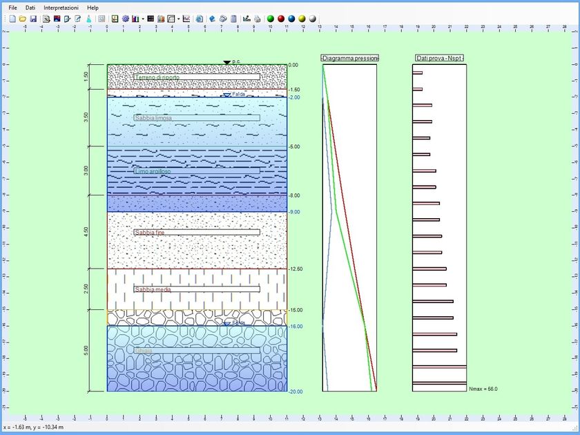
The bedding stratigraphy can be defined for each plinth, managing it by competent areas or by acting plinths.
Once the soil types have been created and assigned and the penetrometric tests associated with them, it is possible to select the mesh points acting on the given stratigraphy. Using S.P.T. and C.P.T. test data, it is possible to further characterise each zone, calculating its short- and long-term subsidence.
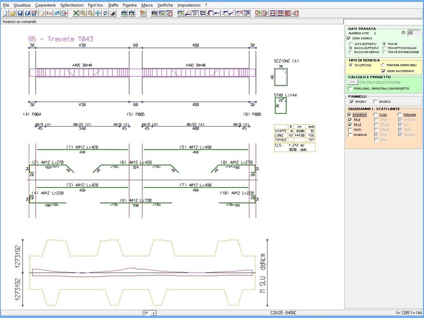
Both the general plan and the reinforcement tables of each plinth can be exported to Dolmen Plan (from which it is possible to create a table with the metric calculation of the reinforcement) and to .dxf.
A visualiser allows the plinth and the abutment to be viewed in 3D, enabling the user to visually verify the arrangement and size of the reinforcement.
It is possible to view and print all the results of the analysis.
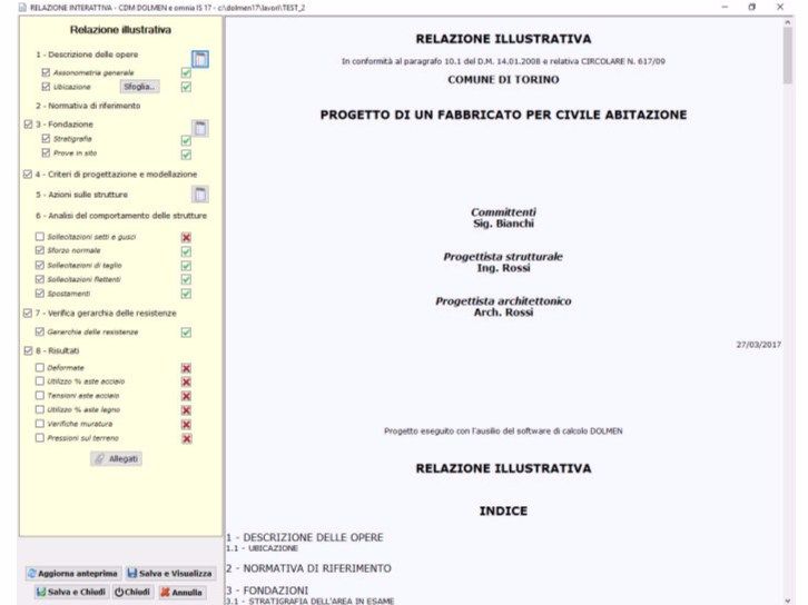
The complete and exhaustive final report, which can be customised in the choice of contents, shows all the design data, the choices made, the verification results and the reinforcement table for each type of plinth designed.
This report can be created in HTML (.html), Word® (.doc) or text (.txt) formats.
21
0